Measure battery voltage
Measure battery level using the ESP32-C3 ADC
🫑 A retrofitted wired audio doorbell with added WiFi connectivity 🔔
Measure battery level using the ESP32-C3 ADC
This code measures the battery voltage using the ESP32-C3 ADC with a voltage divider circuit. The voltage divider circuit is used to scale down the battery voltage to a level that can be measured by the ESP32-C3 ADC. The ESP32-C3 ADC has a 12-bit resolution.
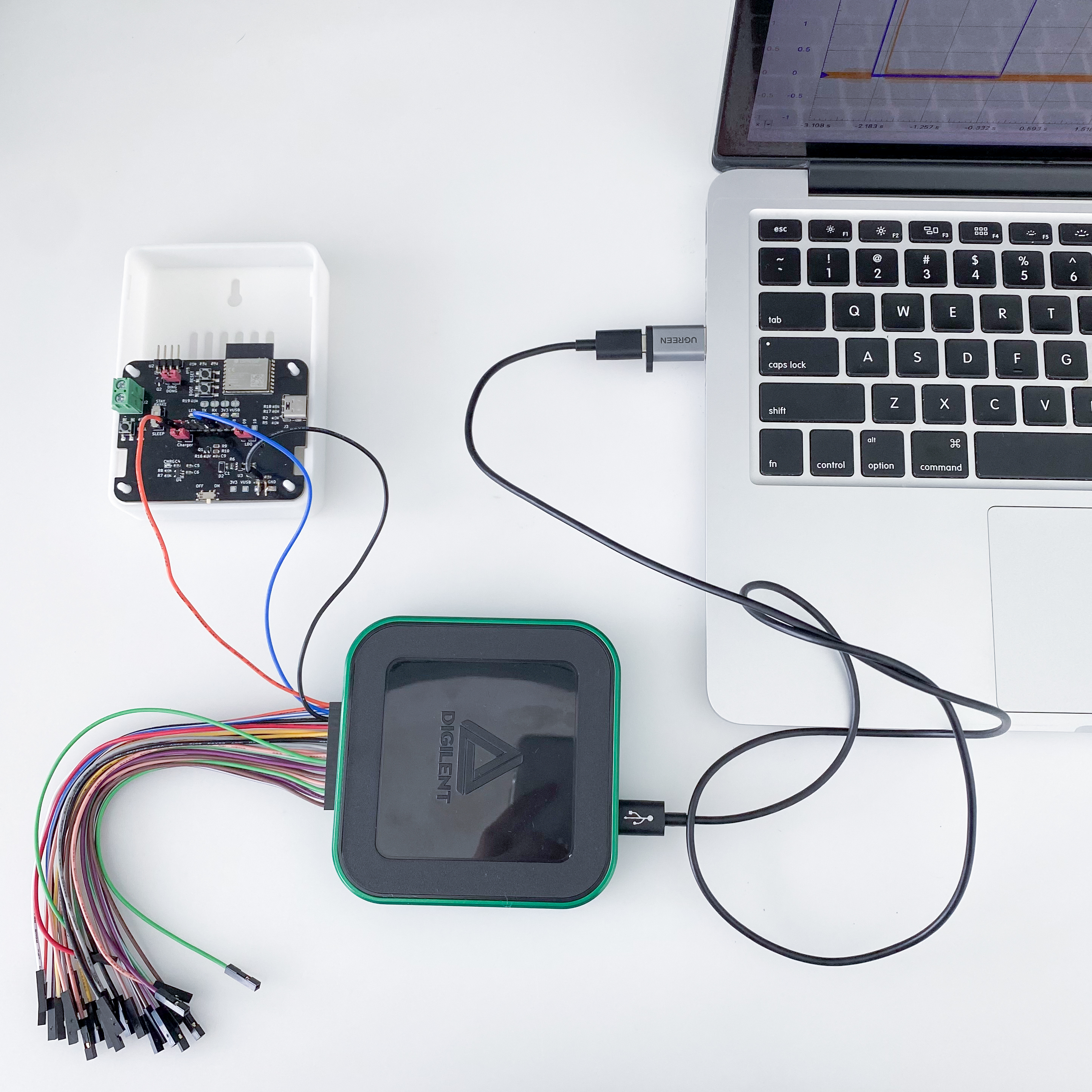
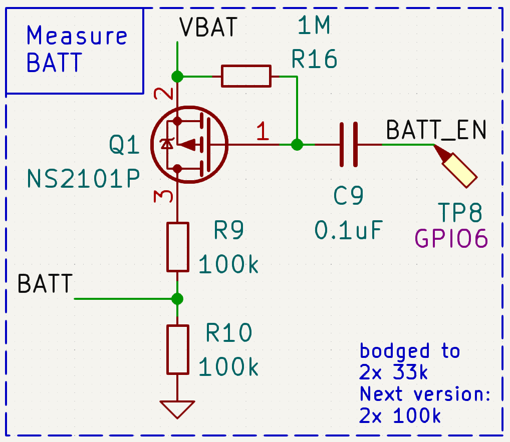
Channel 1 is connected to the BATTERY_ENABLE_PIN where the MOSFET is connected. Channel 2 is connected to the BATTERY_MEASURE_PIN where ADC is connected. Every 2 seconds, the MOSFET is turned on and the battery voltage is measured.
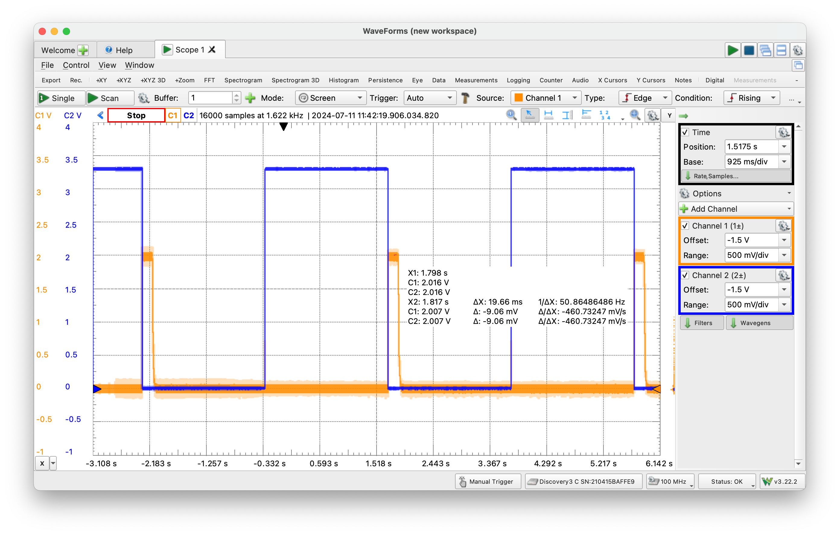
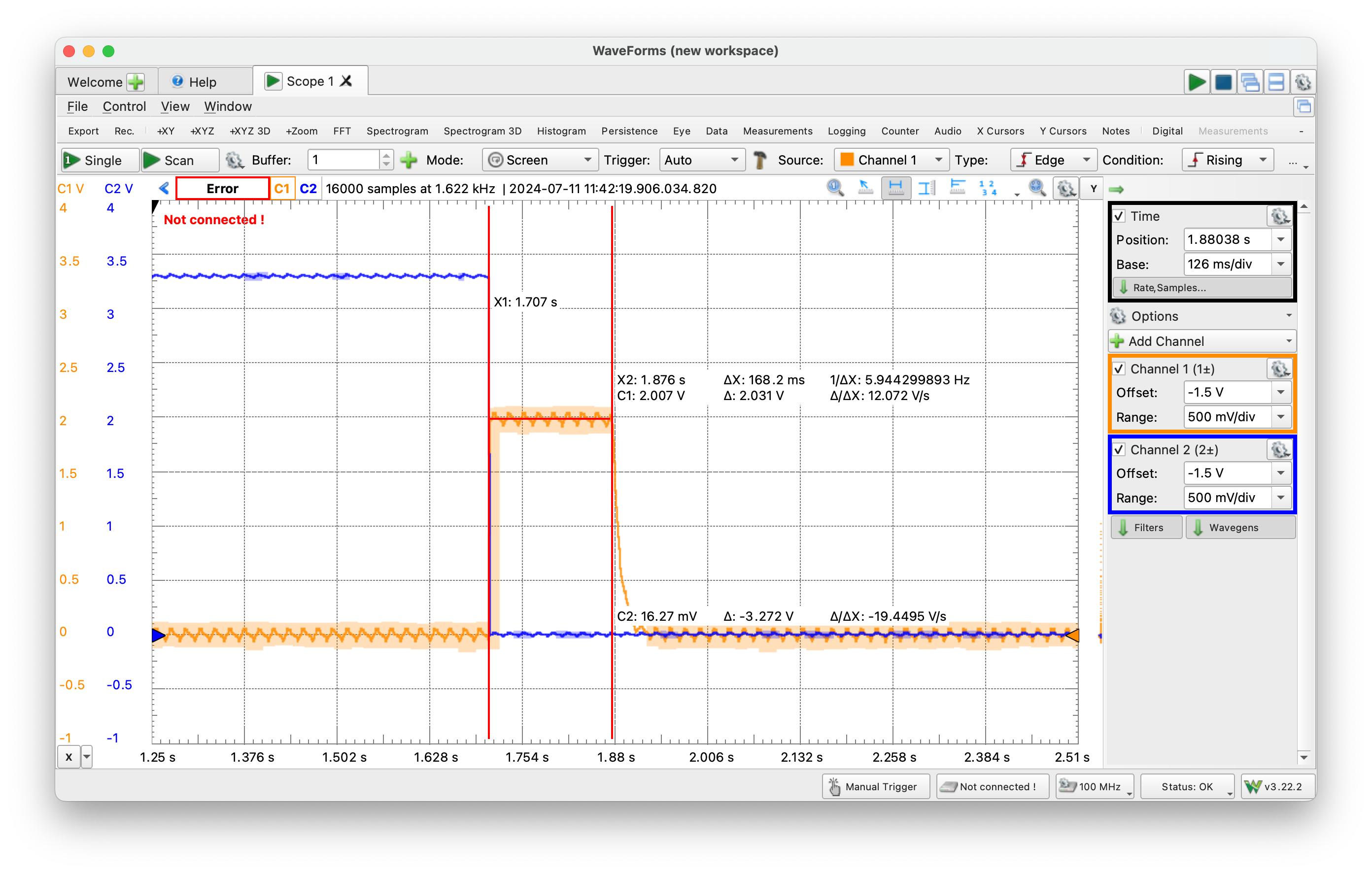
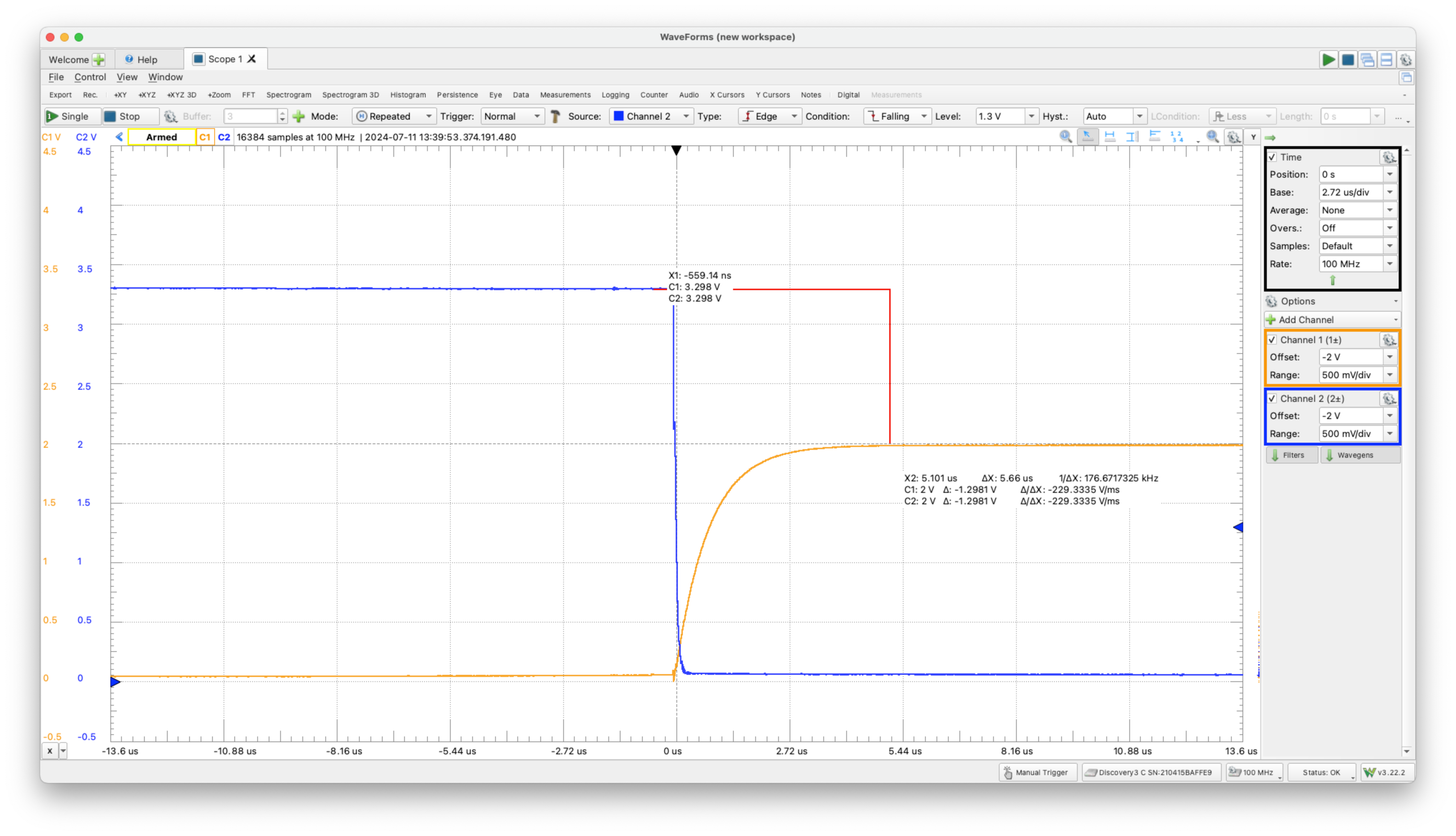
Here the oscilloscope is showing the voltage at pin is 2V and the same is measured by the microcontroller. With the potential divider circuit, the total battery voltage multiplied by 2 and it is 4V. In the code, we add a 10us delay before reading the ADC value.
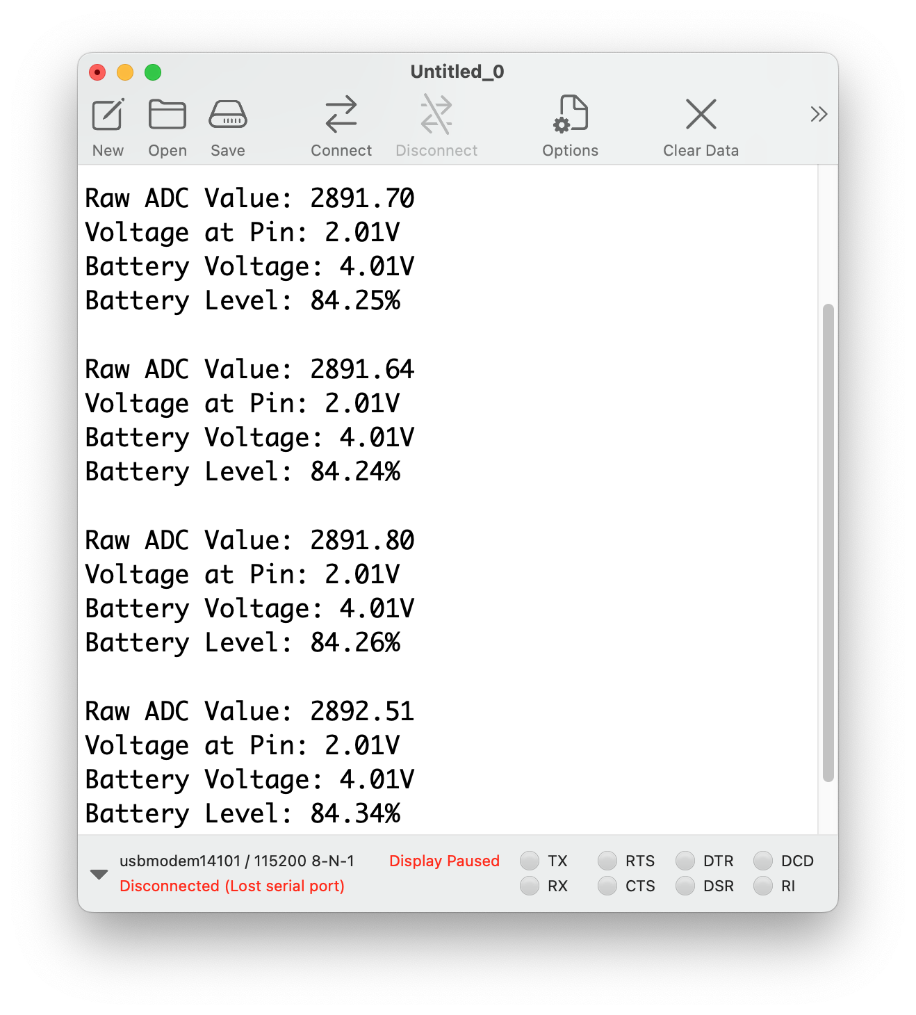
Serial output from the firmware.
Wire up the hardware accordingly
#define LED 3
#define BATTERY_ENABLE_PIN 6
#define BATTERY_MEASURE_PIN 0

const int adcMax = 4095;  // 12-bit ADC resolution

// https://forum.arduino.cc/t/esp32-c3-adc-issue-reading-4095-at-2-8v/1127687/7
const float Vref = 2.86;  // Reference voltage for ADC (2.8V for ESP32-C3)

void setup() {
  Serial.begin(115200);
  Serial.println();

  pinMode(LED, OUTPUT);
  pinMode(BATTERY_ENABLE_PIN, OUTPUT);
  digitalWrite(BATTERY_ENABLE_PIN, HIGH);
}

void loop() {
  digitalWrite(LED, HIGH);

  digitalWrite(BATTERY_ENABLE_PIN, LOW);
  delayMicroseconds(10);
  int sum = 0;

  for (int i = 0; i < 100; i++) {
    sum = sum + analogRead(BATTERY_MEASURE_PIN);
  }
  float adcValue = sum / 100.0;
  Serial.print("Raw ADC Value: ");
  Serial.println(adcValue);

  float voltageAtPin = (adcValue / adcMax) * Vref;
  Serial.print("Voltage at Pin: ");
  Serial.print(voltageAtPin);
  Serial.println("V");

  // 2 is the voltage divider ratio
  // (R1 + R2) / R2)
  float batteryVoltage = voltageAtPin * 2;
  Serial.print("Battery Voltage: ");
  Serial.print(batteryVoltage);
  Serial.println("V");

  // 3.0: Minimum voltage of the battery
  // 4.2: Maximum voltage of the battery
  // 100: Maximum battery level in percentage
  float batteryLevel = (batteryVoltage - 3.0) / (4.2 - 3.0) * 100;
  Serial.print("Battery Level: ");
  Serial.print(batteryLevel);
  Serial.println("%");

  delay(2000);

  digitalWrite(BATTERY_ENABLE_PIN, HIGH);
  digitalWrite(LED, LOW);

  Serial.println();
  delay(2000);
}# Description: Makefile for the demo code
# Usage: make [lint] [compile] [upload] [clean]
BOARD := esp32:esp32:esp32c3:CDCOnBoot=cdc
PORT ?= /dev/cu.usbmodem1410*
BUILD = build
.PHONY: default lint compile upload clean
default: lint compile upload clean
lint:
cpplint --extensions=ino --filter=-legal/copyright,-runtime/int,-readability/todo,-whitespace/line_length *.ino
compile: clean lint
arduino-cli compile --fqbn $(BOARD) --output-dir $(BUILD) ./
upload:
arduino-cli upload --fqbn $(BOARD) --port $(PORT) --input-dir $(BUILD)
clean:
rm -rf build