Blinky
Blink the LED
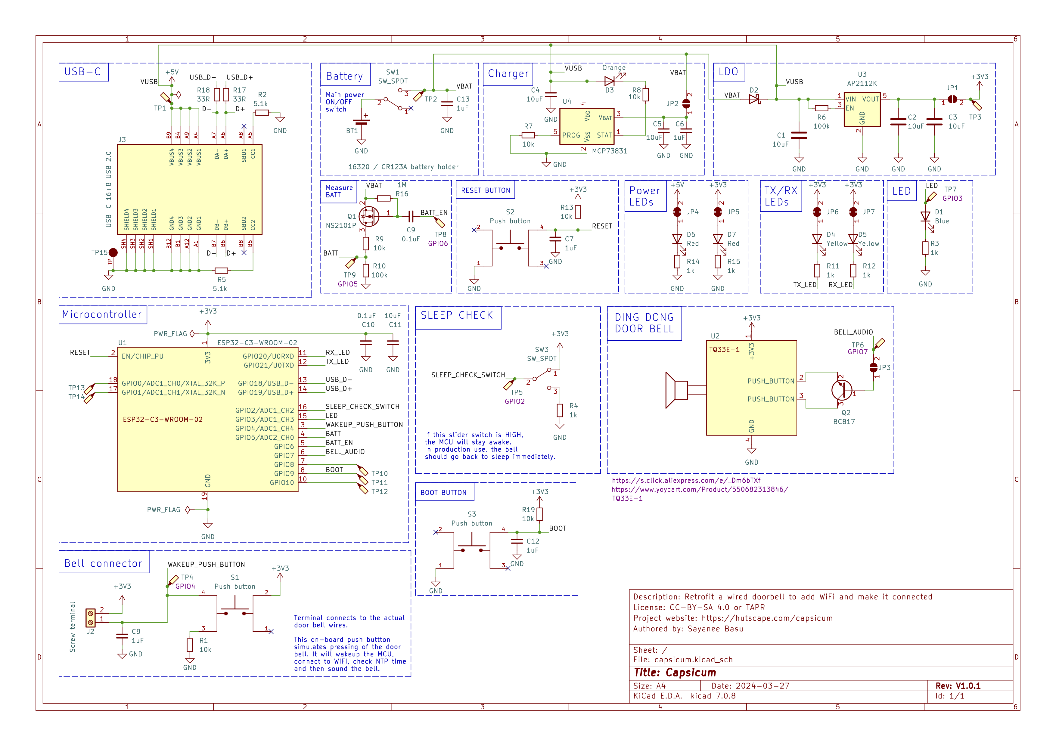
🫑 A retrofitted wired audio doorbell with added WiFi connectivity 🔔
Blink the LED
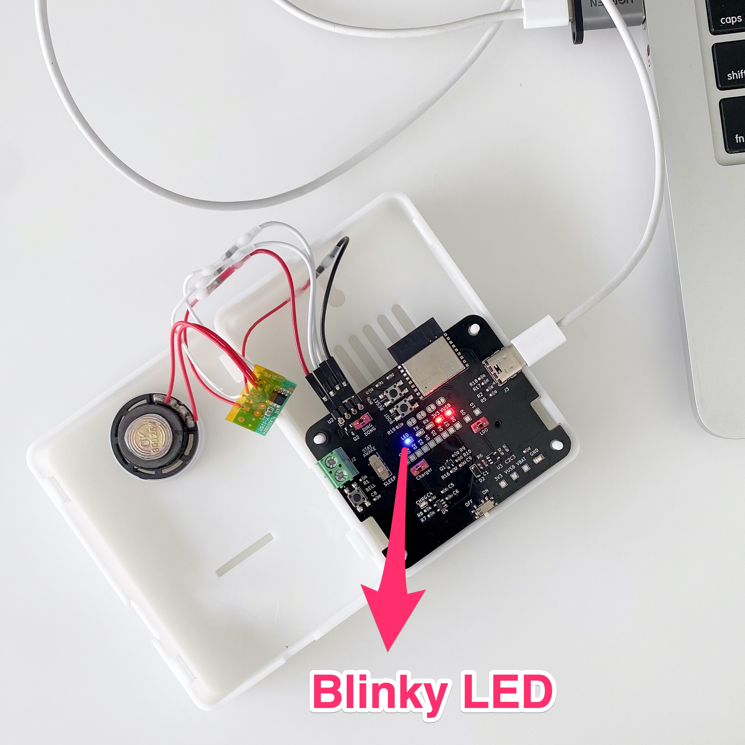
Flash in this simplest blinky code to test the PCB.
On Arduino IDE, enable the option Tools > USB CDC on Boot > Enabled
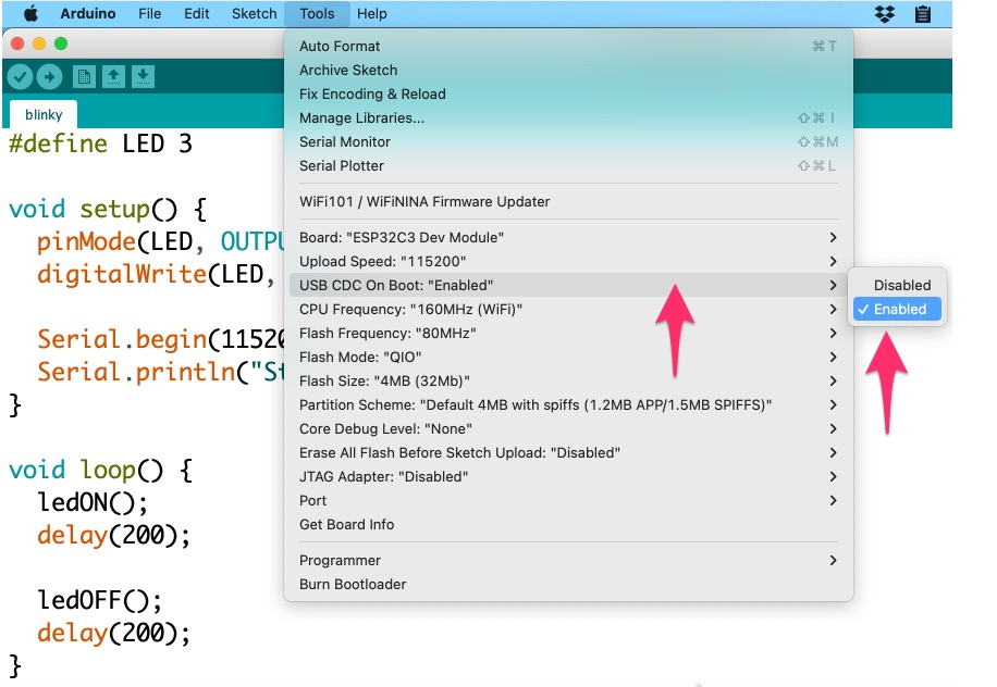
or on arduino-cli, add the FQBN option as --fqbn esp32:esp32:esp32c3:CDCOnBoot=cdc
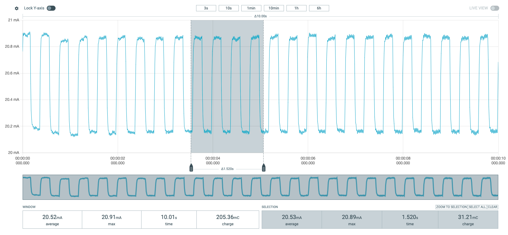
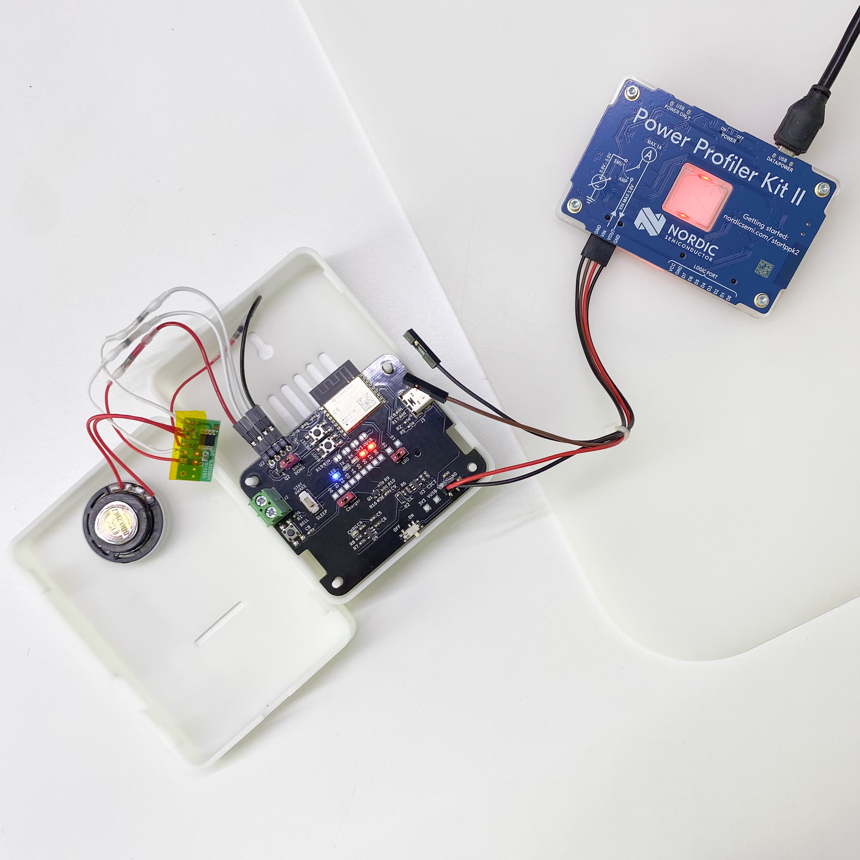
Connect the test points GND and VBAT to nRF Power Profiler kit to measure the power consumption. DO NOT insert the battery in the PCB to ensure the power is only supplied from the nRF Power Profiler kit.
The power consumption of the PCB is around 20.9mA when the LED is on and 20.15mA when the LED is off.
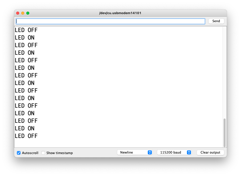
Serial output from the firmware.
Wire up the hardware accordingly
#define LED 3

void setup() {
  pinMode(LED, OUTPUT);
  digitalWrite(LED, LOW);

  Serial.begin(115200);
  Serial.println("Start blinky");
}

void loop() {
  ledON();
  delay(200);

  ledOFF();
  delay(200);
}

void ledON() {
  Serial.println("LED ON");
  digitalWrite(LED, LOW);
}

void ledOFF() {
  Serial.println("LED OFF");
  digitalWrite(LED, HIGH);
}BOARD?=esp32:esp32:esp32c3:CDCOnBoot=cdc
PORT?=/dev/cu.usbmodem1410*
BUILD=build
.PHONY: default lint compile flash clean
default: lint compile flash clean
lint:
cpplint --extensions=ino --filter=-legal/copyright,-runtime/int *.ino
compile: clean lint
arduino-cli compile --fqbn $(BOARD) --output-dir $(BUILD) ./
flash:
arduino-cli upload --fqbn $(BOARD) --port $(PORT) --input-dir $(BUILD)
clean:
rm -rf build