Prototype
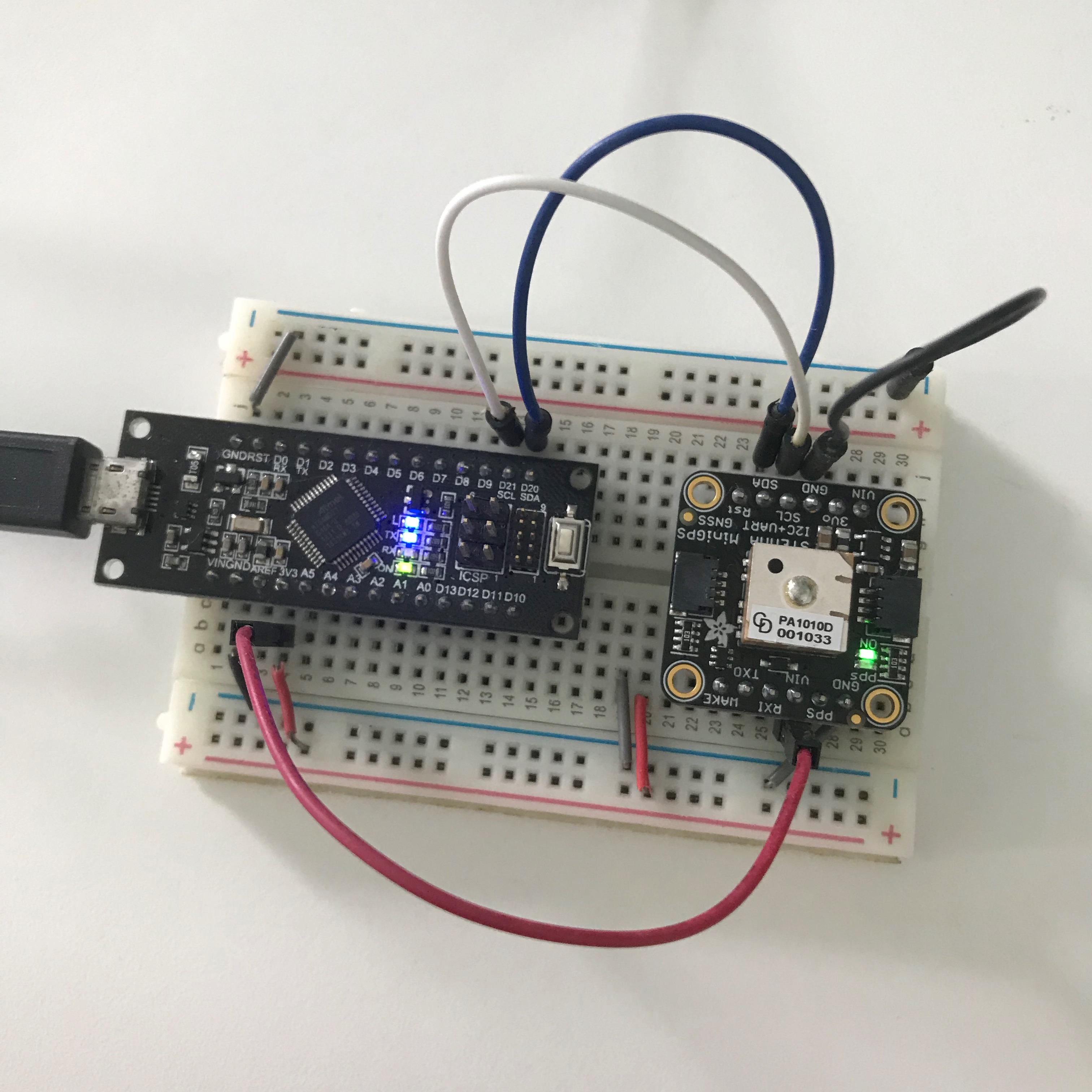
A photo of the actual setup.
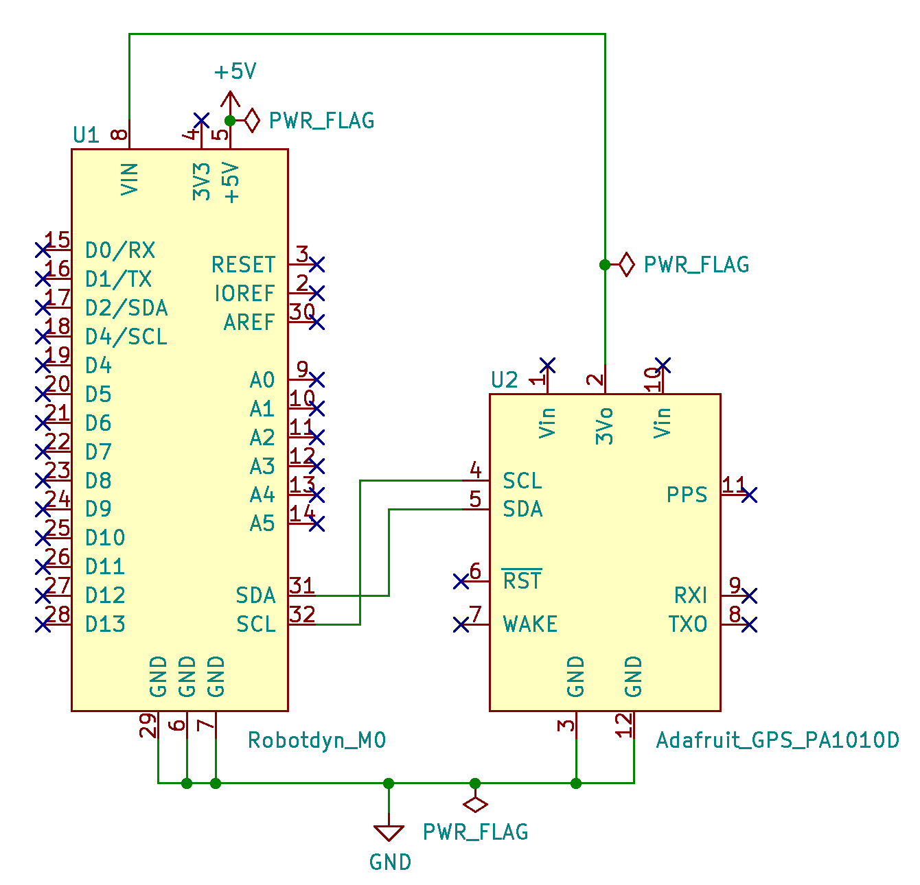
Schematic
Wire up the hardware accordingly
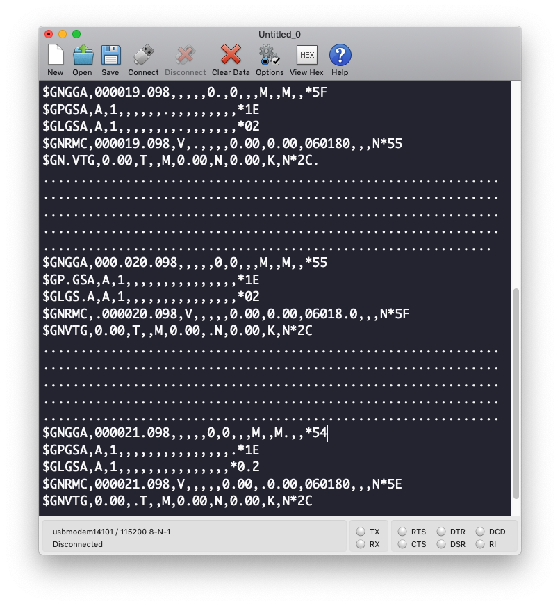
Serial console
Serial output from the firmware.
Dependancies
Pre-requisites
Buy the components
gps-pa1010d-m0-i2c.ino
#include <Adafruit_GPS.h>

Adafruit_GPS GPS(&Wire);

void setup() {
  while (!Serial) {}
  SerialUSB.begin(115200);
  SerialUSB.println("Hello GPS test with I2C!");
  GPS.begin(0x10);  // The I2C address to use is 0x10
}

void loop() {
  if (SerialUSB.available()) {
    char c = SerialUSB.read();
    GPS.write(c);
  }
  if (GPS.available()) {
    char c = GPS.read();
    SerialUSB.write(c);
  }
}BOARD?=arduino:samd:mzero_bl
PORT := $(shell ls /dev/cu.usbmodem*)
.PHONY: default lint all flash clean
default: lint all flash clean
lint:
cpplint --extensions=ino --filter=-legal/copyright,-readability/casting *.ino
all:
arduino-cli compile --fqbn $(BOARD) ./
flash:
arduino-cli upload -p $(PORT) --fqbn $(BOARD) ./
clean:
rm -f .*.bin
rm -f .*.elf
rm -f .*.hexA photo of the actual setup.
Wire up the hardware accordingly
Serial output from the firmware.
Use Adafruit GPS module PA1010D with Arduino M0 (with micro-controller SAMD21G) to display parsed GPS data via the I2C protocol.