Quality
For future improvements
- (Schematci) Add functional logical blocks in schematic to use similar circuits in future versions or other projects
- (Manufacturing) Use stencil SMD soldering with SMD components only if it is necessary. Else, use a PCB assembly service.
- (Manufacturin) Use minimum number of through-hole components
- (Manufacturing) Check Gerber file format with the PCB manufacturer before rendering them
-
(Manufacturing) Check
F.PasteandB.Pastelayers for SMD stencil pattern - (Testing) Pull out every single MCU pin as a test point for the first version of the project.
-
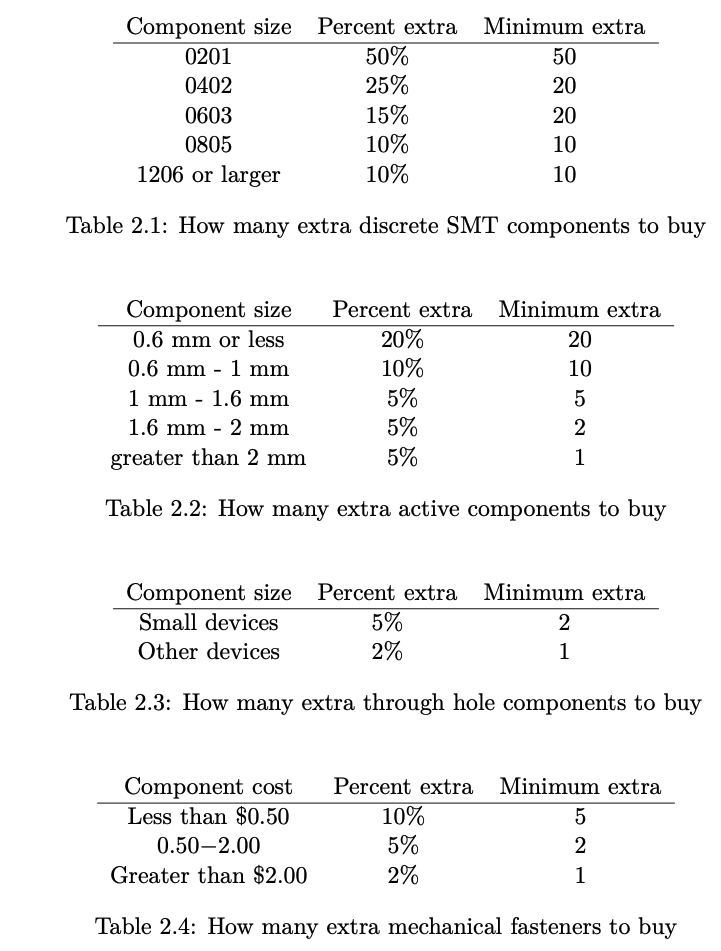
(BOM) Always buy buffer number of components. Image is from the book Designing Electronics That Work by Hunter Scott.
- (Layout) Make the PCB routing symmetrical for LED positions and connector slots
- (Case) Ensure the length is not too long to prevent bending of the material
- (Case) Use wider ventilation holes with wider spacing between each of them
- (Case) Use less clearance for connector slots. Take note of finger access
- (Case) Use other shapes for connector slots E.g. rounded corner or trapezoid
- (Case) Use shape binder for seperation plane bends
- (Case) Use a counter sunk screw head
- (Case) Make the screw lug's initial length be wider to contain the screw head so that it can sink into the surface
- (Case) Try a snap-fit enclosure
- (Manufacturing) Use SMD components only on top layer for one-step manual SMD stencil soldering process
- (Layout) Place a writable area on the silkscreen to note down LoRa node address, PCB number, frequency or other info
-
(Layout) Add a surface mount PCB test point for
VBAT,VBUS,3.3V,5V,GNDand SPI points. -
(BOM) Use a smaller
SSD1306I2C OLED display instead of E-Ink. It's cheaper and easier to source and buy. - (Testing) Check with 3 PCBs to conclude whether it is a design issue or a soldering / manufacturing / assembly issue
-
(Testing) Power it with current limiting power supply unit only. Check all the power test points such as
VBAT,VBUS,3.3V,5V,GND.