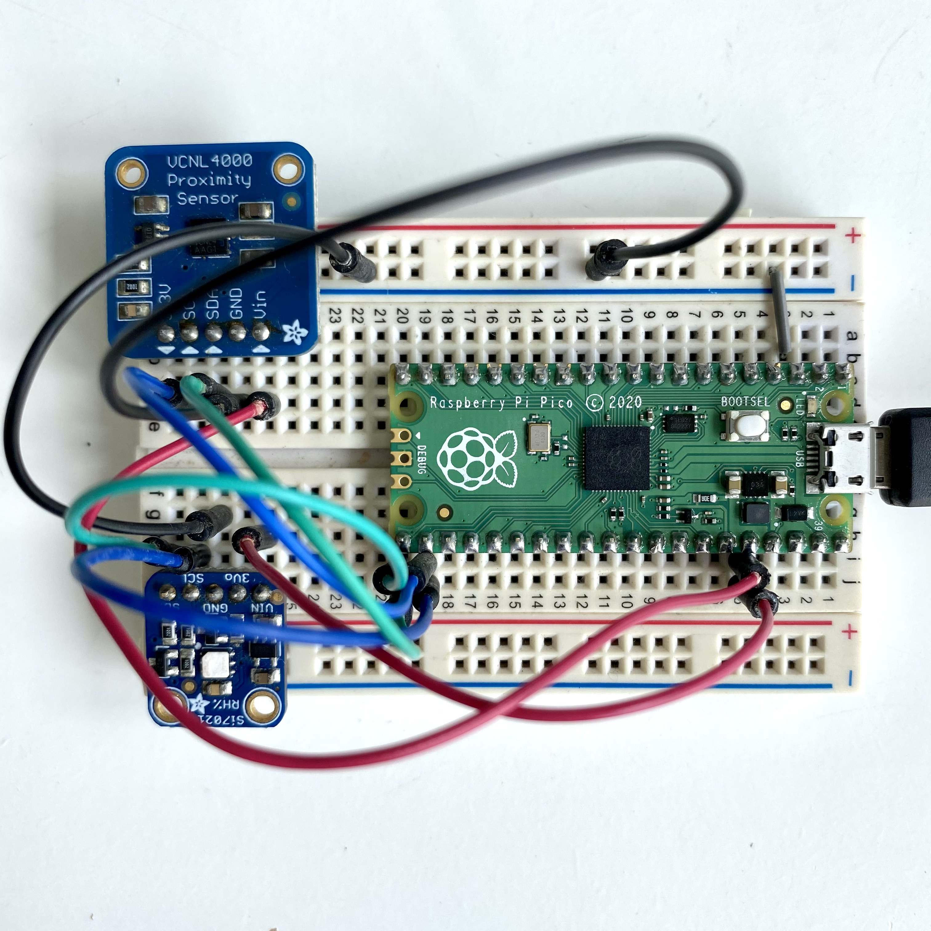
Prototype
A photo of the actual setup.
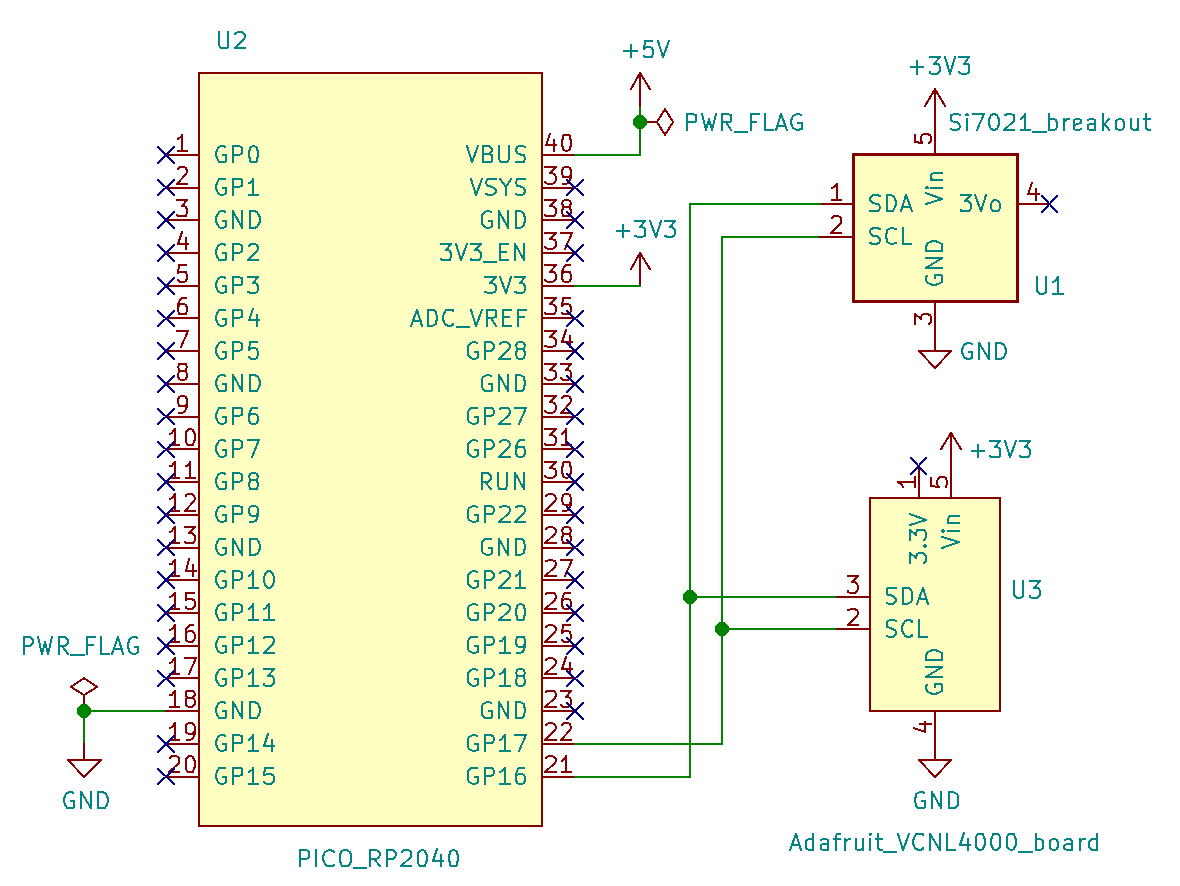
Schematic
Wire up the hardware accordingly
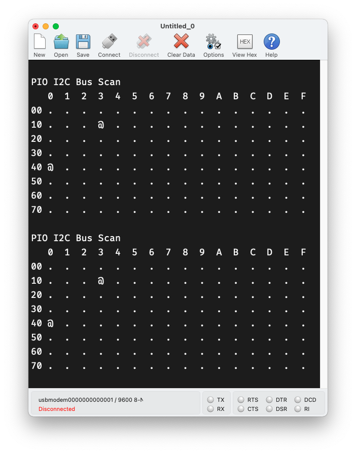
Serial console
Serial output from the firmware.
Dependancies
Pre-requisites
Buy the components
pico-pio-i2c.c
#include <stdio.h>
#include "pico/stdlib.h"
#include "pio_i2c.h"

#define PIN_SDA 16
#define PIN_SCL 17

bool reserved_addr(uint8_t addr) {
  return (addr & 0x78) == 0 || (addr & 0x78) == 0x78;
}

int main() {
  stdio_init_all();

  PIO pio = pio0;
  uint sm = 0;
  uint offset = pio_add_program(pio, &i2c_program);
  i2c_program_init(pio, sm, offset, PIN_SDA, PIN_SCL);

  while (true) {
    printf("\nPIO I2C Bus Scan\n");
    printf("   0  1  2  3  4  5  6  7  8  9  A  B  C  D  E  F\n");

    for (int addr = 0; addr < (1 << 7); ++addr) {
      if (addr % 16 == 0) {
        printf("%02x ", addr);
      }

      int result;
      if (reserved_addr(addr))
        result = -1;
      else
        result = pio_i2c_read_blocking(pio, sm, addr, NULL, 0);

      printf(result < 0 ? "." : "@");
      printf(addr % 16 == 15 ? "\n" : "  ");
    }

    sleep_ms(2000);
  }
}A photo of the actual setup.
Wire up the hardware accordingly
Serial output from the firmware.
This example code does an I2C Bus Scan for the sensors Si7021 and VCNL4000 with PIO.
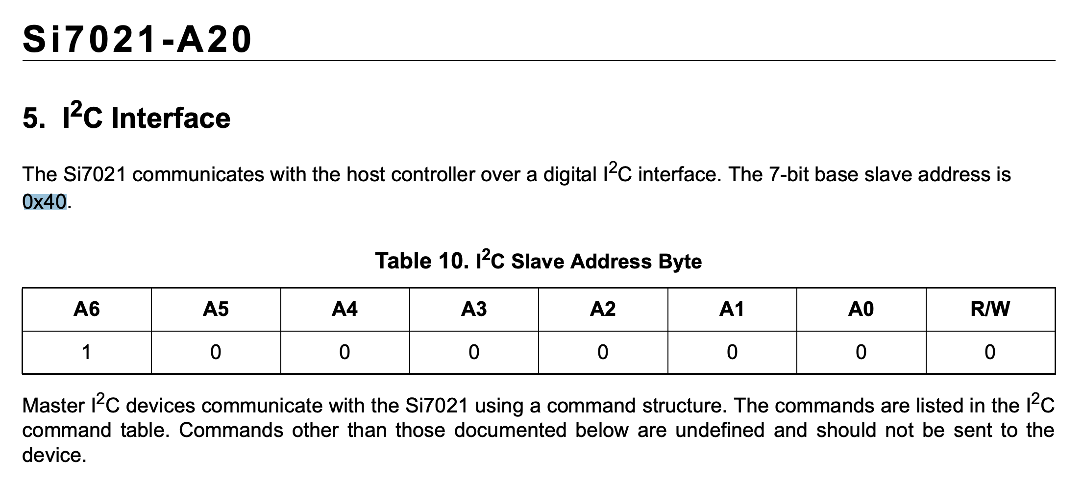
The datasheets of the 2 sensors below show that the serial monitor prints are in line with the information in the datasheet.
The I2C address for Si7021 is 0x40.
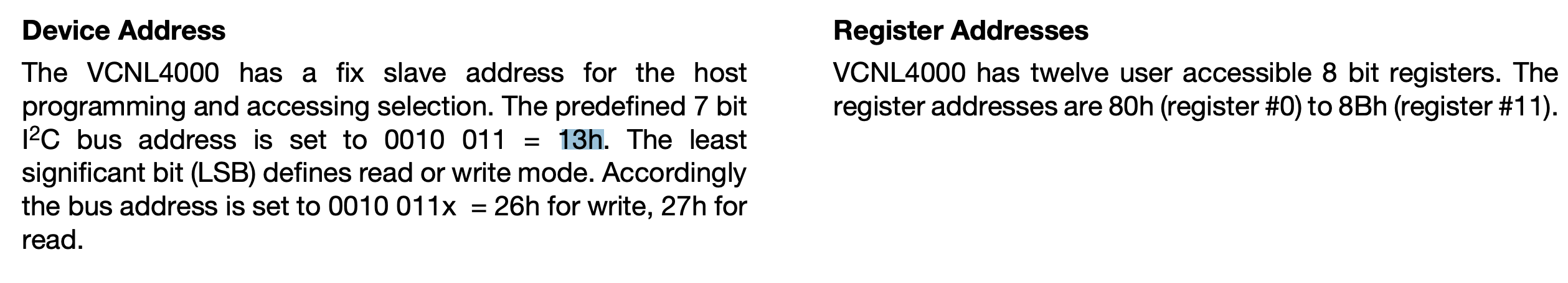
The I2C address for VCNL4000 is 0x13.