Prototype
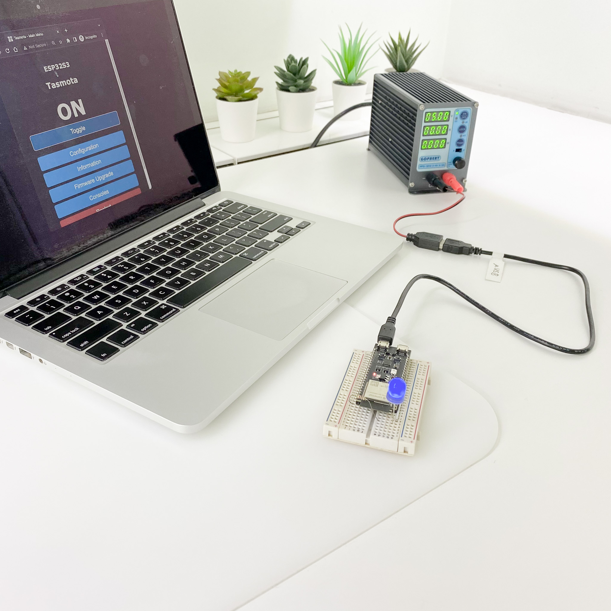
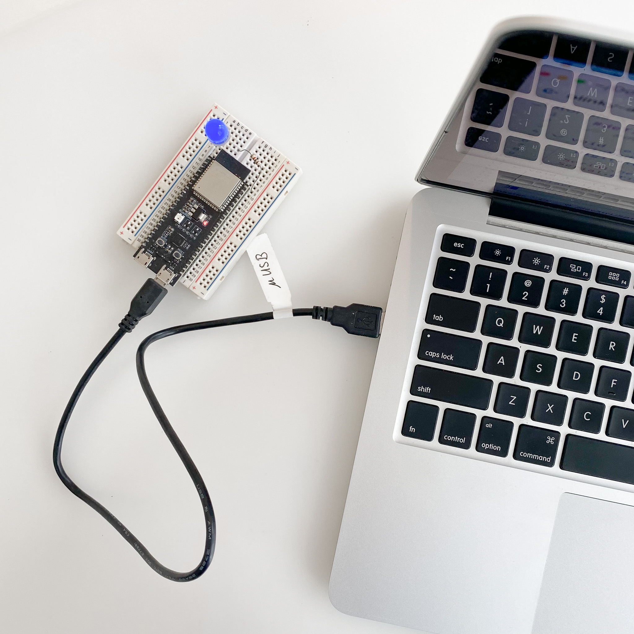
A photo of the actual setup.
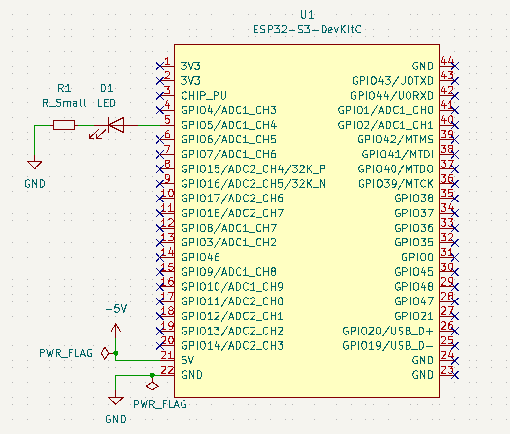
Schematic
Wire up the hardware accordingly
Dependancies
Pre-requisites
A photo of the actual setup.
Wire up the hardware accordingly
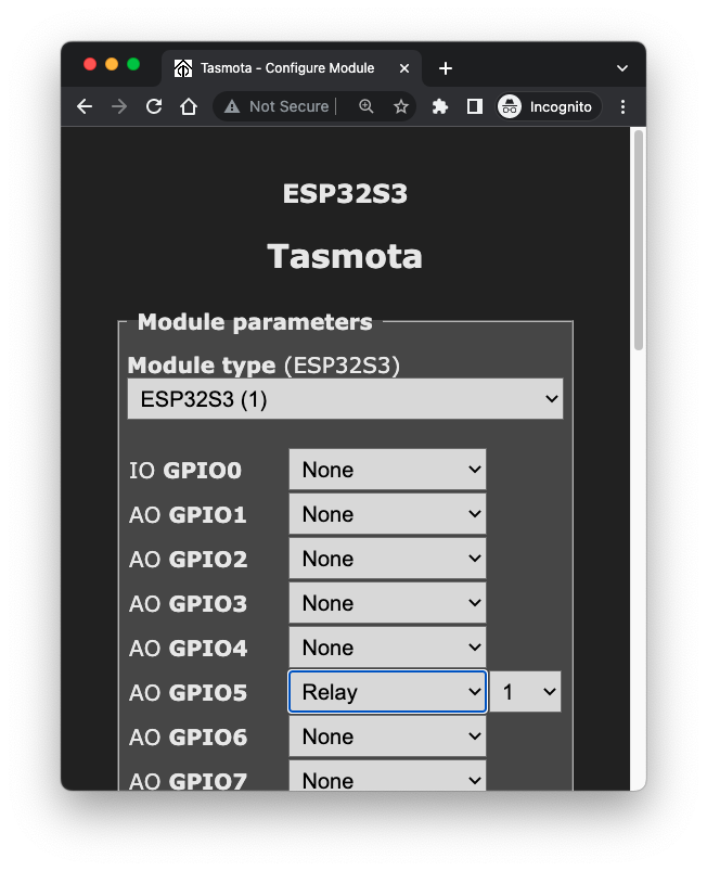
Use GPIO5 to add a simple external LED
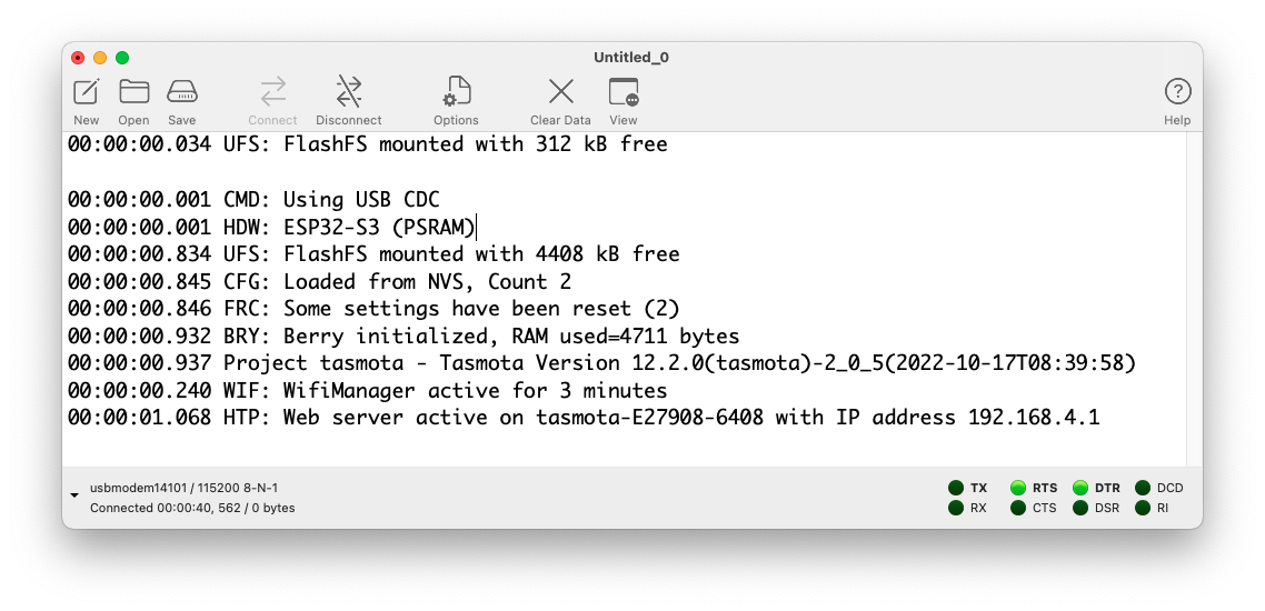
tasmota32s3cdc.factory.bin from ESP32 current releasePlug into the USB port of the board and check the address
 $ ls /dev/cu.*
 /dev/cu.Bluetooth-Incoming-Port  /dev/cu.usbmodem14101
Erase the flash memory with esptool.py
$ esptool.py --port /dev/cu.usbmodem14101 erase_flash
Flash the binary using esptool.py
$ esptool.py --port /dev/cu.usbmodem14101 write_flash --flash_mode dio --flash_size 4MB 0x0 tasmota32s3cdc.factory.bin
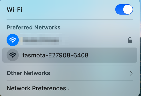
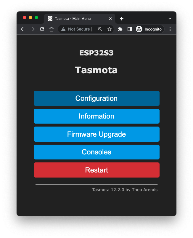
tasmota-
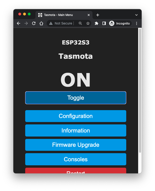
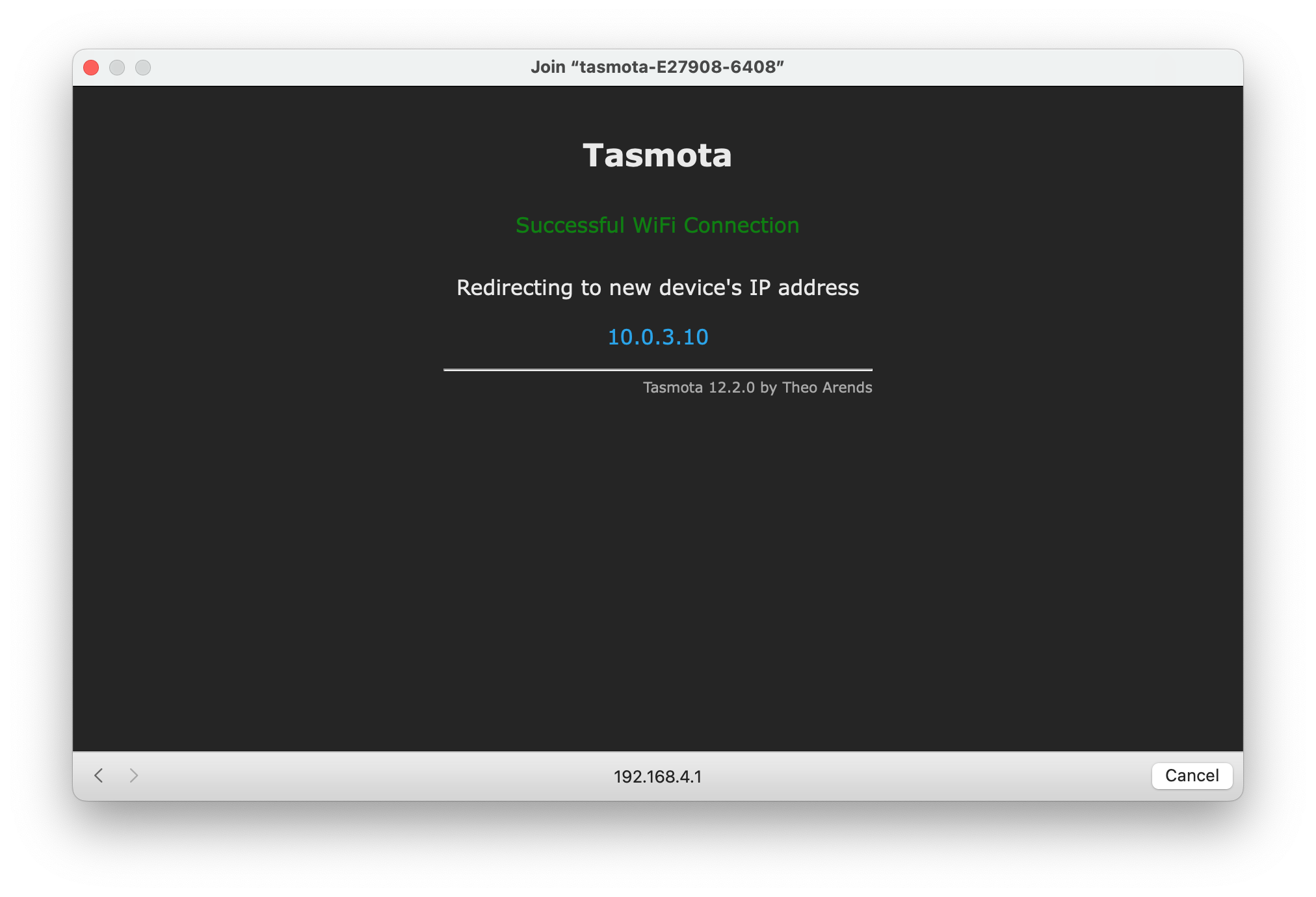
10.0.3.10 in the browser
GPIO5

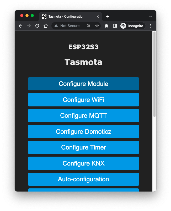
Configuration
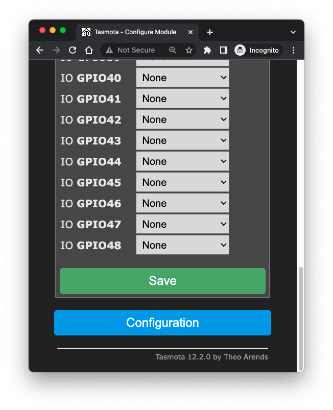
Configure Module
GPIO5 to Relay number 1
http://10.0.3.10/cm?cmnd=GPIO to see the configuration change in GPIO5
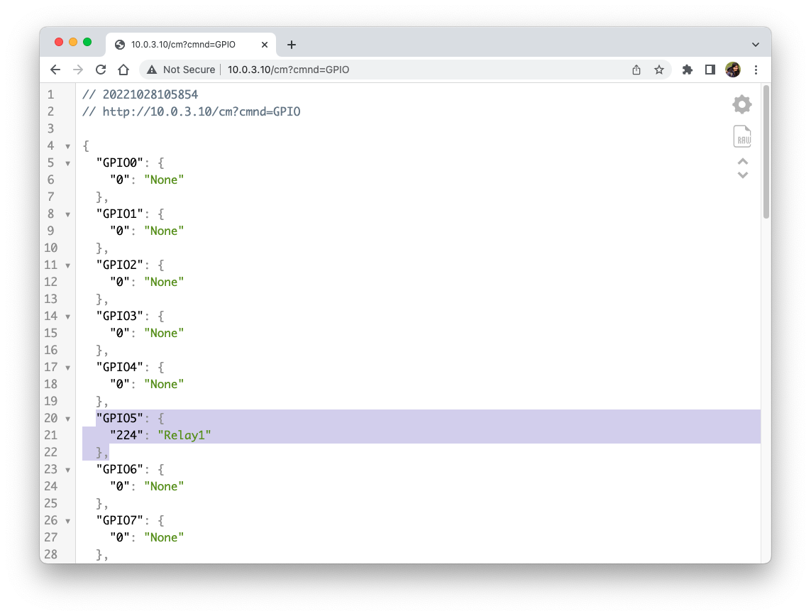
ON and OFF to control the LED