Prototype
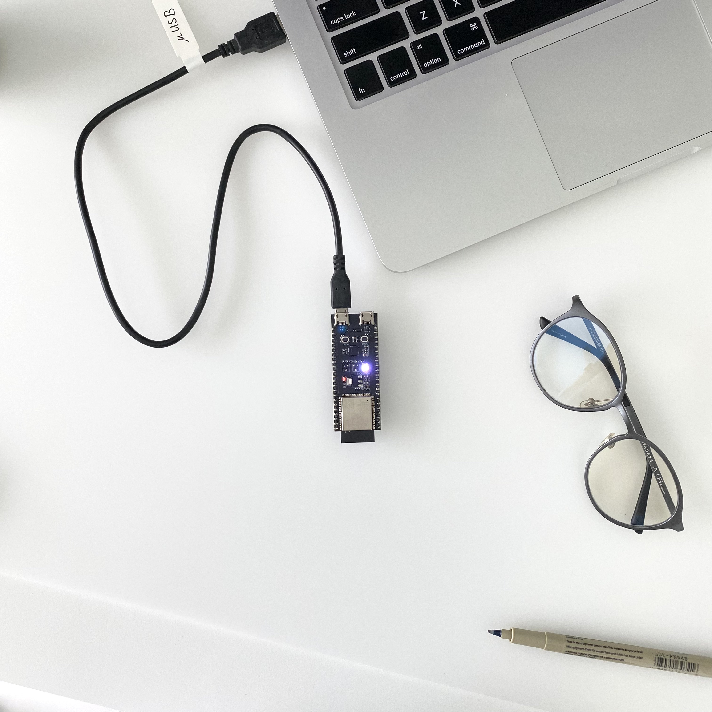
A photo of the actual setup.
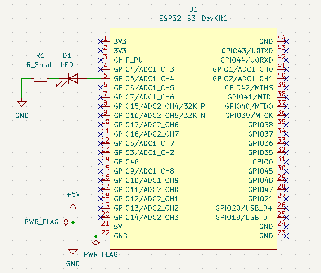
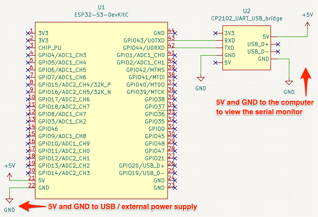
Schematic
Wire up the hardware accordingly
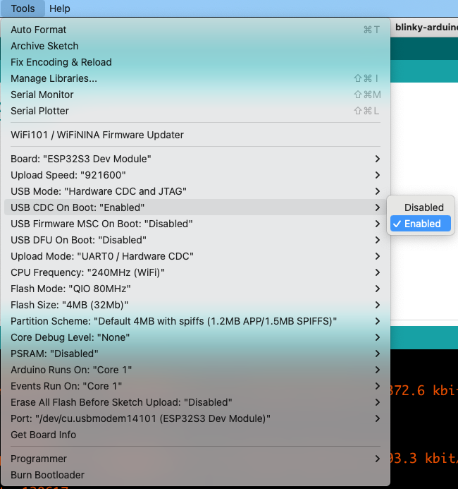
Arduino IDE settings
Ensure the following IDE settings before flashing.
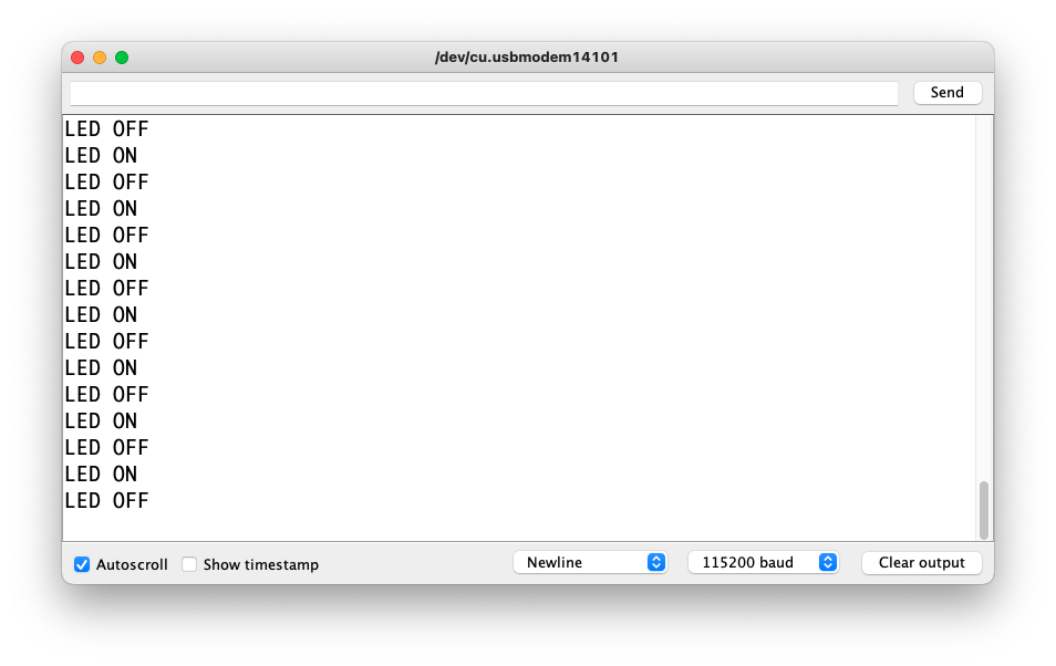
Serial console
Serial output from the firmware.
Dependancies
Pre-requisites
blinky-arduino-esp32s3.ino
#define LED LED_BUILTIN
// #define LED 5

void setup() {
  pinMode(LED, OUTPUT);
  digitalWrite(LED, LOW);

  Serial.begin(115200);
  Serial.println("Start blinky");
}

void loop() {
  ledON();
  delay(200);

  ledOFF();
  delay(200);
}

void ledON() {
  Serial.println("LED ON");
  digitalWrite(LED, LOW);
}

void ledOFF() {
  Serial.println("LED OFF");
  digitalWrite(LED, HIGH);
}BOARD?=esp32:esp32:esp32s3:CDCOnBoot=cdc
PORT?=/dev/cu.usbmodem14*
BUILD=build
## Pass in V=--verbose to output more information than default
.PHONY: help default lint compile upload clean
default: clean lint compile upload
help: ## Show help message
@awk 'BEGIN {FS = ":.*##"; printf "\nUsage:\n make \033[36m\033[0m\n"} /^[$$()% 0-9a-zA-Z_-]+:.*?##/ { printf " \033[36m%-15s\033[0m %s\n", $$1, $$2 } /^##@/ { printf "\n\033[1m%s\033[0m\n", substr($$0, 5) } ' $(MAKEFILE_LIST)
lint: ## Lint code using cpplint
cpplint --extensions=ino --filter=-legal/copyright *.ino
compile: ## Compile code and create the firmware binary
arduino-cli compile $(V) --fqbn $(BOARD) --output-dir $(BUILD) ./
upload: ## Upload the firmware to the board
arduino-cli upload $(V) --fqbn $(BOARD) --port $(PORT) --input-dir $(BUILD)
# terminal command from Arduino IDE
# "~/Library/Arduino15/packages/esp32/tools/esptool_py/4.2.1/esptool" --chip esp32s3 --port "/dev/cu.usbmodem14101" --baud 921600 --before default_reset --after hard_reset write_flash -z --flash_mode dio --flash_freq 80m --flash_size 4MB 0x0 "/path/to/code/blinky-esp32s3.ino.bootloader.bin" 0x8000 "/path/to/code/blinky-esp32s3.ino.partitions.bin" 0xe000 "~/Library/Arduino15/packages/esp32/hardware/esp32/2.0.5/tools/partitions/boot_app0.bin" 0x10000 "/path/to/code/blinky-esp32s3.ino.bin"
# terminal command from arduino-cli
# ~/Library/Arduino15/packages/esp32/tools/esptool_py/4.2.1/esptool" --chip esp32s3 --port "/dev/tty.usbmodem14101" --baud 921600 --before default_reset --after hard_reset write_flash -z --flash_mode dio --flash_freq 80m --flash_size 4MB 0x0 "build/blinky-esp32s3.ino.bootloader.bin" 0x8000 "build/blinky-esp32s3.ino.partitions.bin" 0xe000 "~/Library/Arduino15/packages/esp32/hardware/esp32/2.0.5/tools/partitions/boot_app0.bin" 0x10000 "build/blinky-esp32s3.ino.bin
clean: ## Remove all built files
rm -rf buildA photo of the actual setup.
Wire up the hardware accordingly
Ensure the following IDE settings before flashing.
Serial output from the firmware.

Use GPIO5 to add a simple external LED
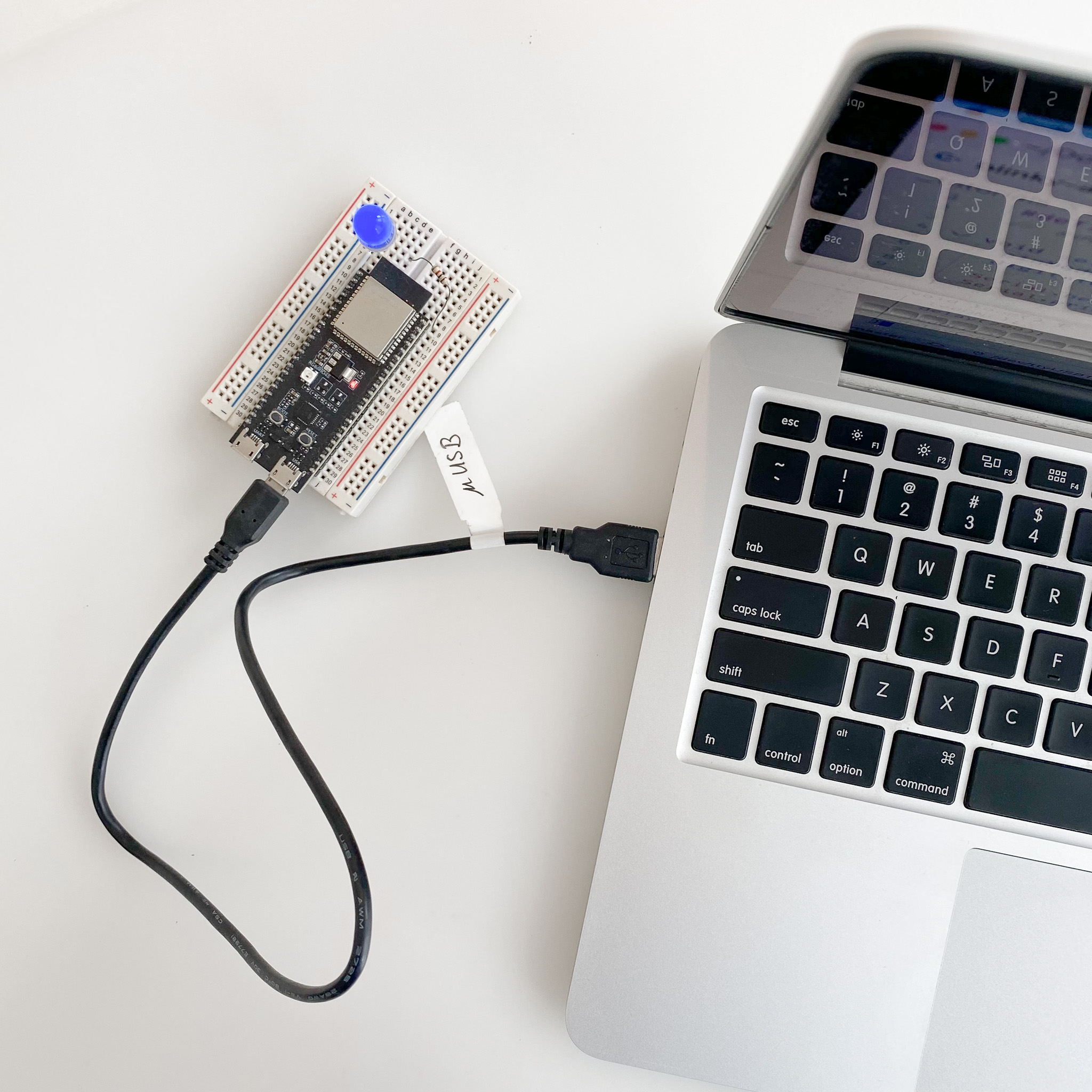
Use GPIO5 to add a simple external LED
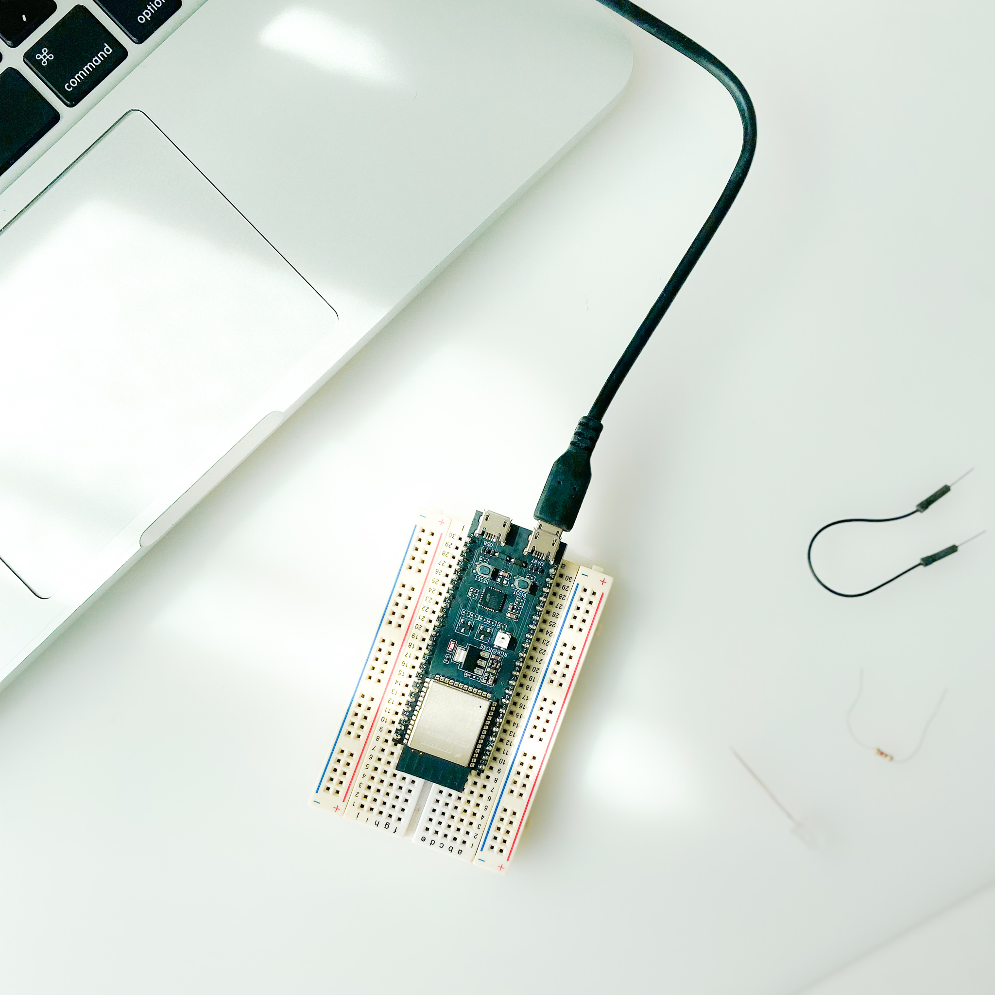
Change to the UART port to view the serial monitor

Setup of using an external USB power with an UART-USB bridge to the computer
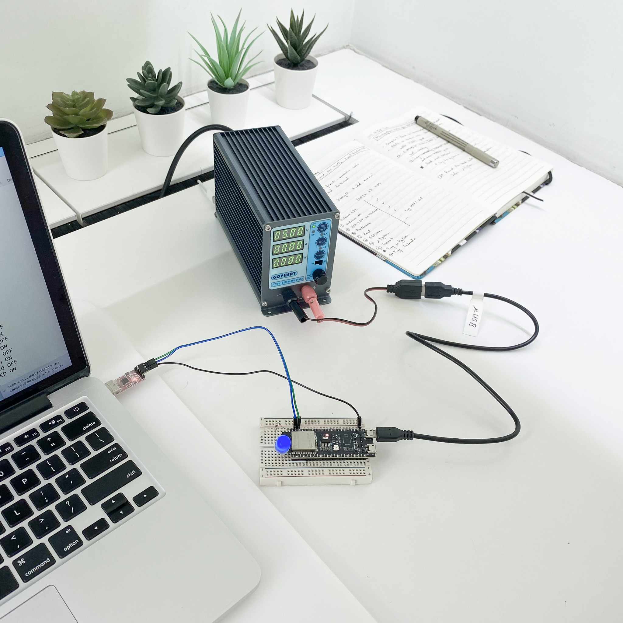
Setup of using an external power supply with an UART-USB bridge to the computer
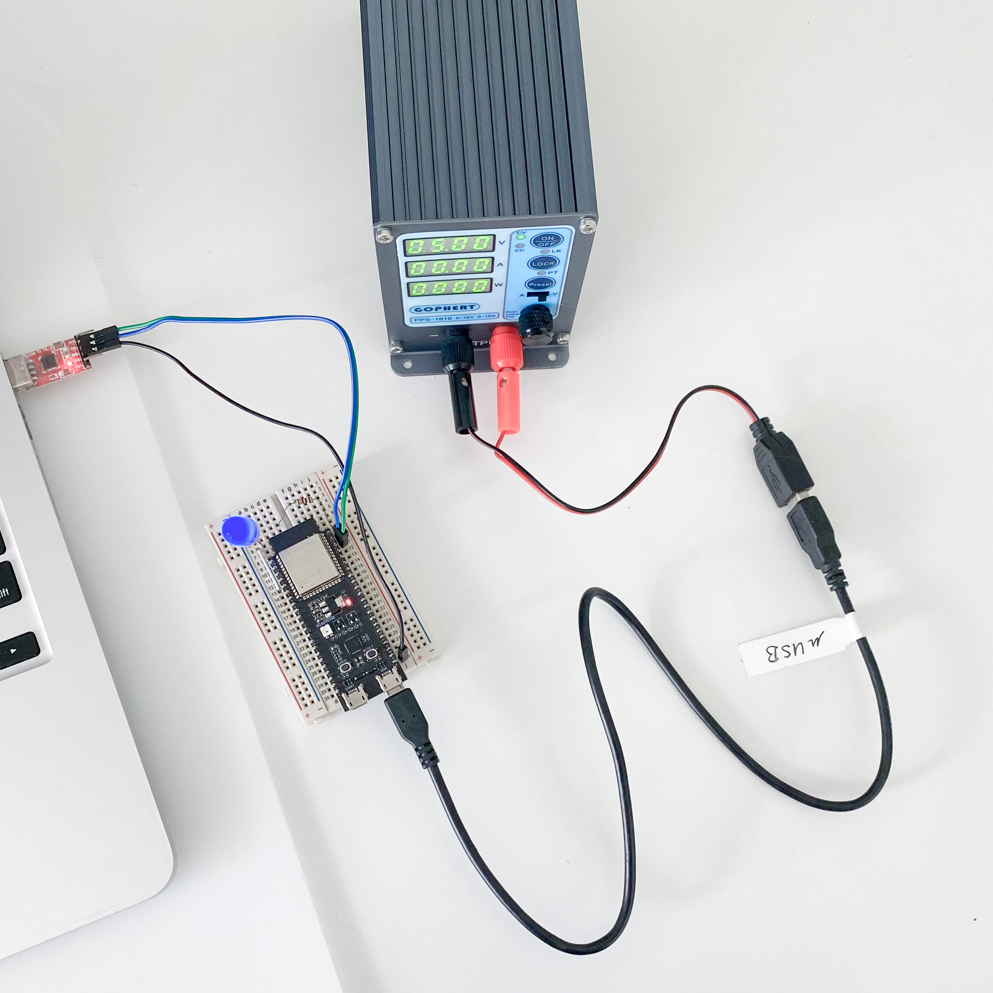
Setup of using an external power supply with an UART-USB bridge to the computer
LED_BUILTIN is pin 48 as defined in the Arduino variant and schematic.
Alternatively #define LED 5 can be used as well to test a simpler LED.

USB and UARTPlug into the USB port and check the addresses
 $ ls /dev/cu.*

 /dev/cu.Bluetooth-Incoming-Port  /dev/cu.usbmodem14101
USB port for example, /dev/cu.usbmodem14101 with USB CDC on Boot enabled or disabled:
UART port or TX/RX with an external UART-to-USB bridgeUSB port
USB port.USB CDC on Boot disabled.Unplug and plug into the UART port and check the address
 $ ls /dev/cu.*

 /dev/cu.Bluetooth-Incoming-Port  /dev/cu.SLAB_USBtoUART  /dev/cu.usbserial-1410
/dev/cu.usbserial-1410 when plugged into UARTUse this option when using an external power supply for the board.
USB port of the board to the computer.USB CDC on Boot disabled.USB port and into the power supply unit.TX, RX and GND to an external USB-UART bridge connected to the computer.
UART port and check the address
 $ ls /dev/cu.*

 /dev/cu.Bluetooth-Incoming-Port  /dev/cu.SLAB_USBtoUART  /dev/cu.usbserial-1410
/dev/cu.usbserial-1410USB port.USB CDC on Boot enabled.
USB portUSB CDC on Boot Enabled on Arduino IDE
arduino-cli with --fqbn esp32:esp32:esp32s3:CDCOnBoot=cdc