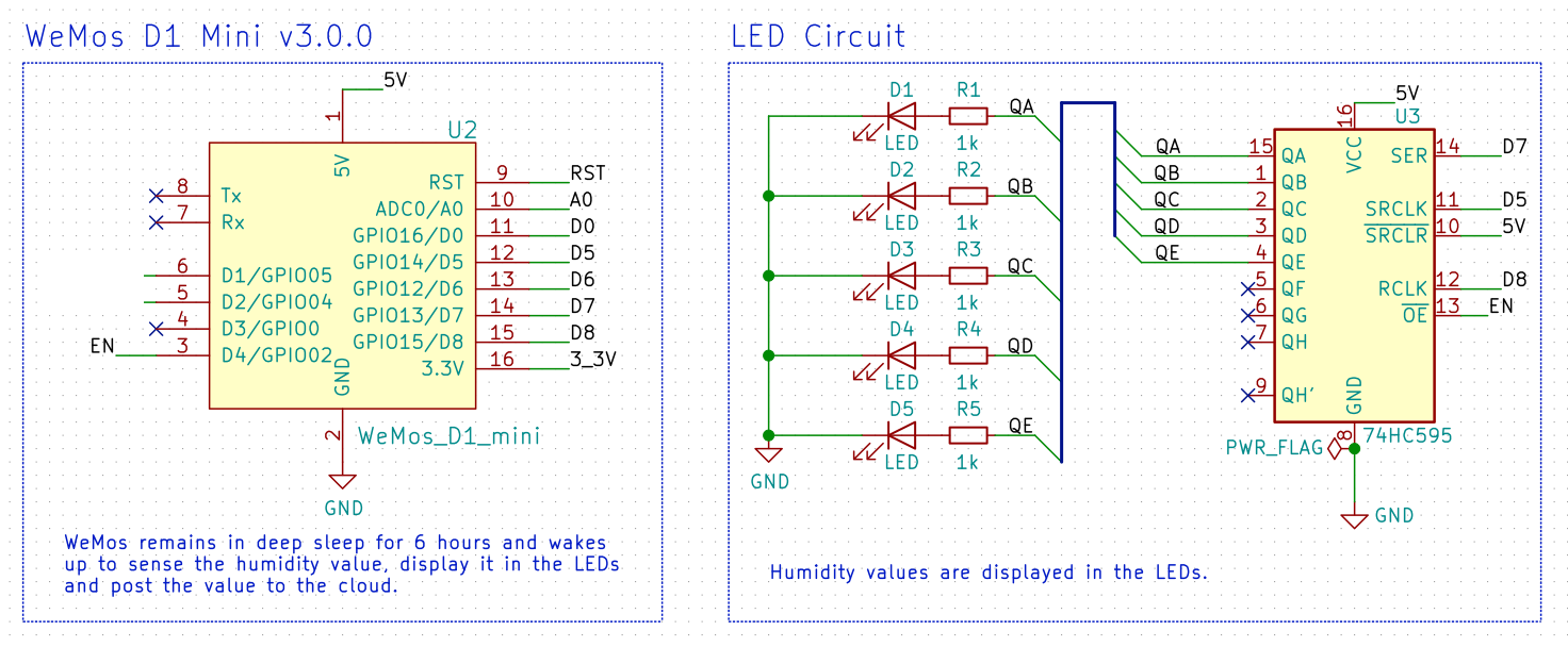
Schematic
Wire up the hardware accordingly
Dependancies
Pre-requisites
Buy the components
shift-register.ino
#define EN 2 // GPIO02 on ESP-01 module, D4 on nodeMCU WeMos

int dataPin = 13; // pin D7 `GPIO13` on NodeMCU boards
int clockPin = 14; // pin D5 `GPIO14` on NodeMCU boards
int latchPin = 15; // pin D8 `GPIO15` on NodeMCU boards

void setup() {
  pinMode(latchPin, OUTPUT);
  pinMode(clockPin, OUTPUT);
  pinMode(dataPin, OUTPUT);

  pinMode(EN, OUTPUT);
  digitalWrite(EN, LOW); // enable shift register
}

void loop() {
  for (int numberToDisplay = 0; numberToDisplay < 256; numberToDisplay++) {
    digitalWrite(latchPin, LOW);
    shiftOut(dataPin, clockPin, MSBFIRST, numberToDisplay);
    digitalWrite(latchPin, HIGH);

    Serial.begin(115200);
    Serial.println(numberToDisplay);
    delay(500);
  }
}BOARD?=esp8266com:esp8266:d1_mini
PORT?=/dev/cu.wchusbserial1410
BUILD=build
# Arduino CLI version 0.14.0 is used.
.PHONY: default lint all flash clean
default: lint all flash clean
lint:
cpplint --extensions=ino --filter=-legal/copyright *.ino
all:
arduino-cli compile --fqbn $(BOARD) --output-dir $(BUILD) ./
flash:
arduino-cli upload --fqbn $(BOARD) --port $(PORT) --input-dir $(BUILD)
clean:
rm -r buildWire up the hardware accordingly
Display LED as a bar graph going from 1 LED ON to all 5 LEDs ON.