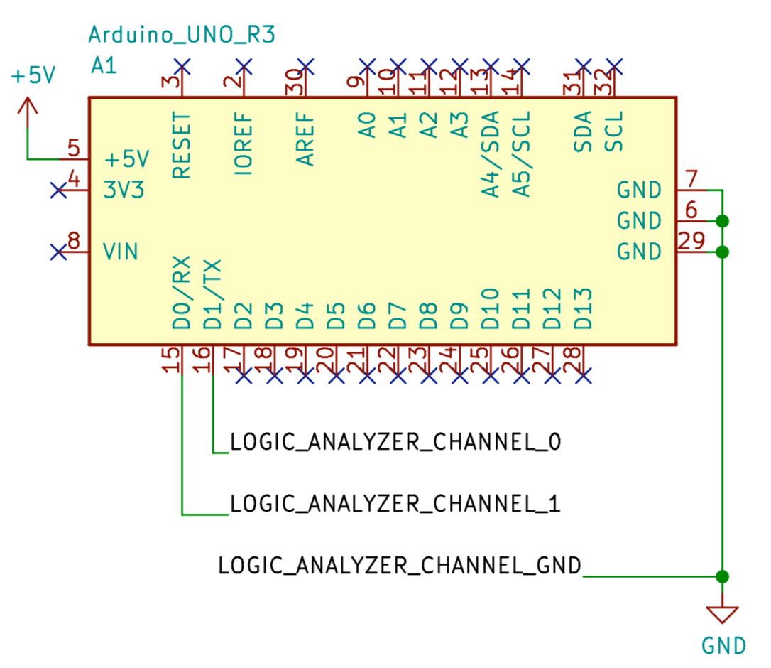
Schematic
Wire up the hardware accordingly
Buy the components
logic-analyzer-uart.ino
void setup() {
  Serial.begin(9600);
  delay(1000);
}

void loop() {
  Serial.println("hello");
  delay(2000);
}BOARD?=arduino:avr:uno
PORT?=/dev/cu.usbmodem14*
.PHONY: default lint all flash clean
default: lint all flash clean
lint:
cpplint --extensions=ino --filter=-legal/copyright *.ino
all:
arduino-cli compile --fqbn $(BOARD) ./
flash:
arduino-cli upload -p $(PORT) --fqbn $(BOARD) ./
clean:
rm -f .*.hex
rm -f .*.elfWire up the hardware accordingly
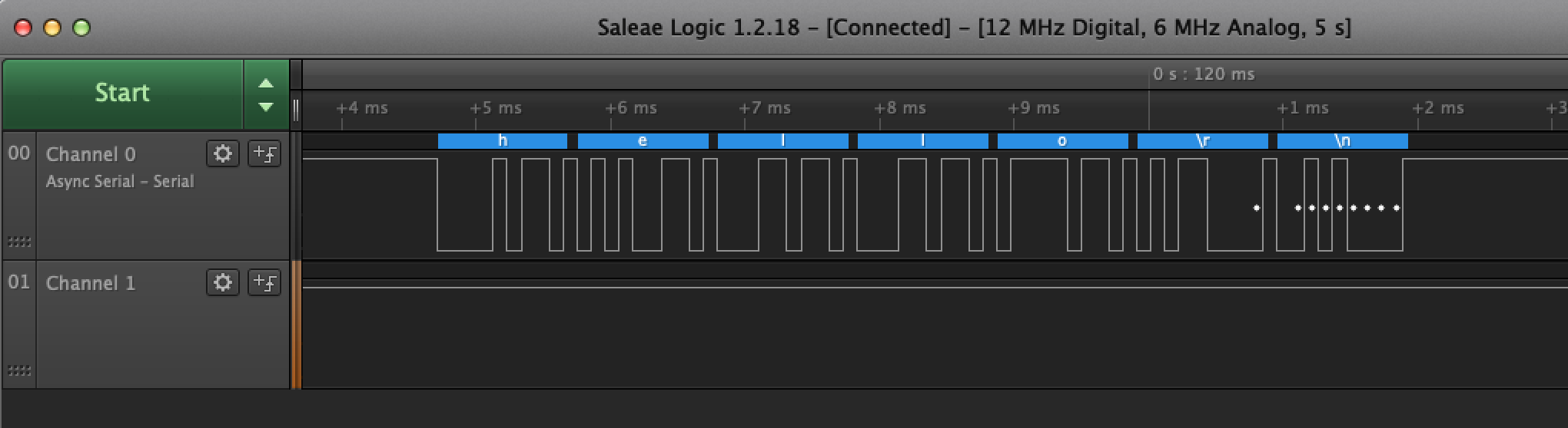
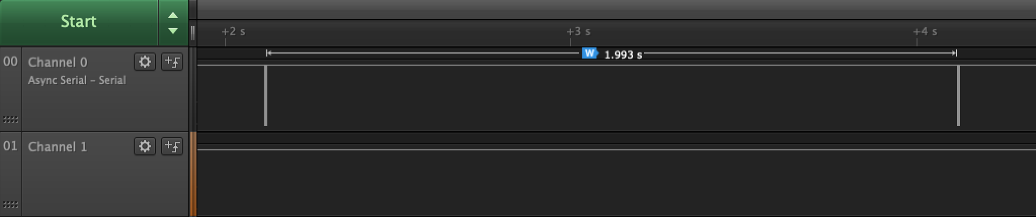
View the decoded asynchronous serial signal from the graph produced by Saleae.
Capture the signal in Saleae:
Add asynchronous serial to decode the captured signal: