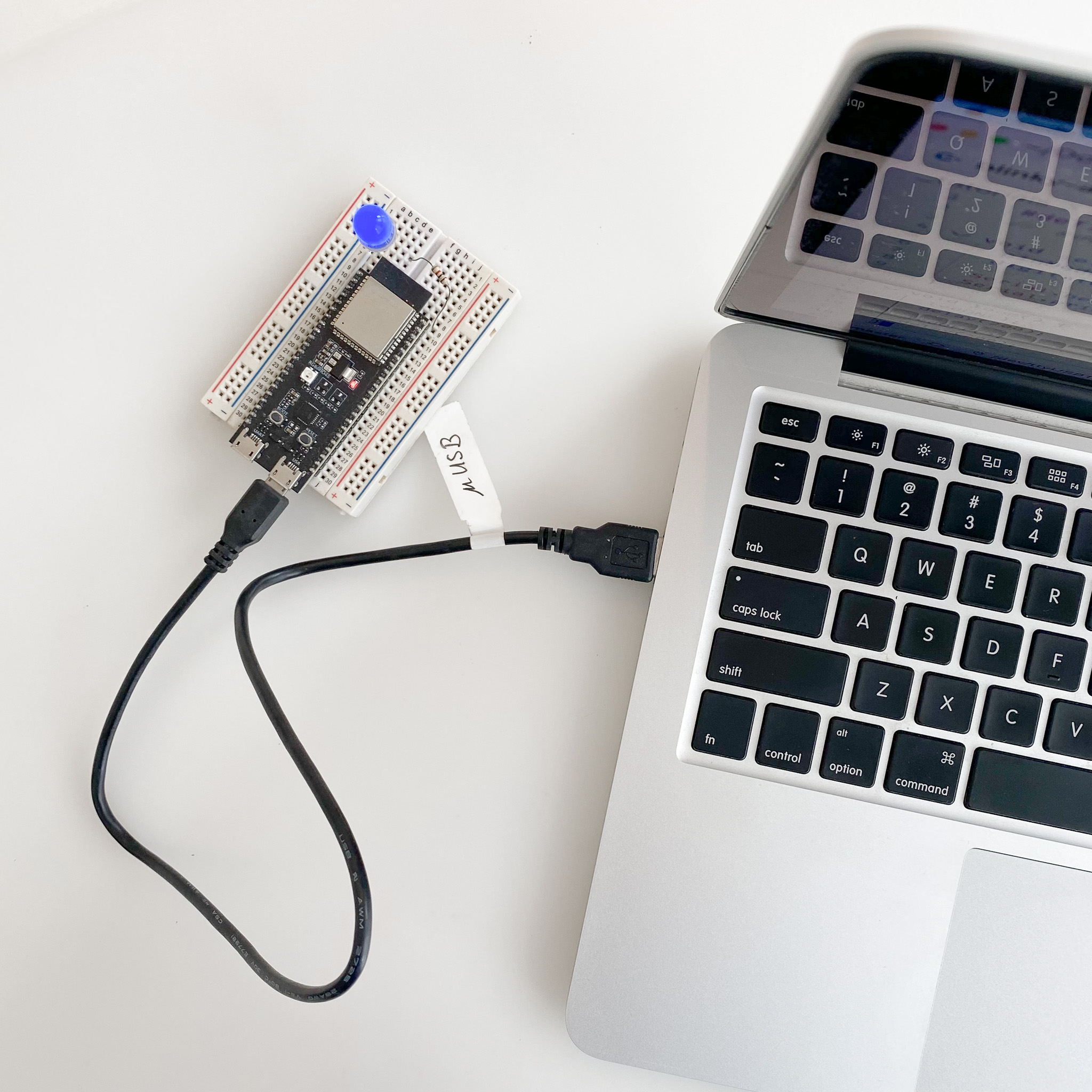
Prototype
A photo of the actual setup.

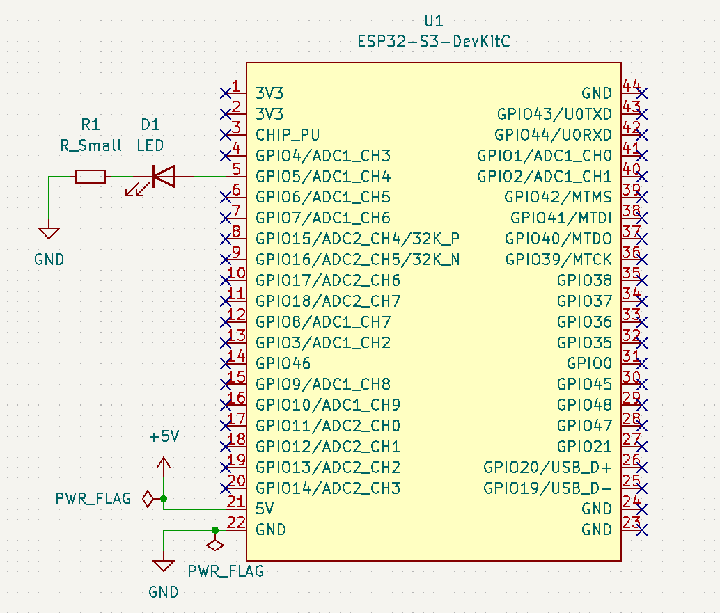
Schematic
Wire up the hardware accordingly
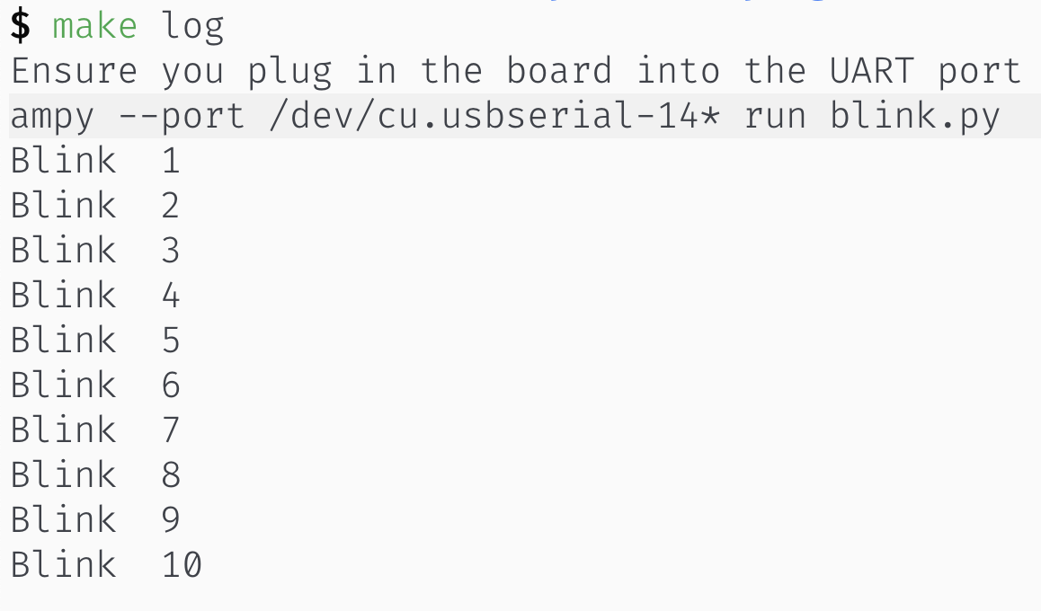
Serial console
Serial output from the firmware.
Dependancies
Buy the components
blink.py
from machine import Pin
import time
led_pin = 5  # Default on-board RGB LED GPIO48 does not work

led = Pin(led_pin, Pin.OUT)
for i in range(10):
  led.on()
  time.sleep_ms(500)
  led.off()
  time.sleep_ms(500)
print("Blink ", i+1)PYTHON_FILE=blink.py
BIN_FILENAME=GENERIC_S3-20220618-v1.19.1.bin
UPLOAD_PORT?=/dev/cu.usbmodem14*
SERIAL_PORT?=/dev/cu.usbserial-14*
.PHONY: help default upload log
default: upload
help: ## Show help message
@awk 'BEGIN {FS = ":.*##"; printf "\nUsage:\n make \033[36m\033[0m\n"} /^[$$()% 0-9a-zA-Z_-]+:.*?##/ { printf " \033[36m%-15s\033[0m %s\n", $$1, $$2 } /^##@/ { printf "\n\033[1m%s\033[0m\n", substr($$0, 5) } ' $(MAKEFILE_LIST)
upload: ## Erase flash and then upload the micropython binary
@echo "Ensure you plug in the board into the USB port"
@ls /dev/cu.*
esptool.py --chip esp32s3 --port $(UPLOAD_PORT) erase_flash
esptool.py --chip esp32s3 --port $(UPLOAD_PORT) write_flash -z 0 $(BIN_FILENAME)
log: ## Access the serial monitor with ampy
@ls /dev/cu.*
@echo "Ensure you plug in the board into the UART port"
ampy --port $(SERIAL_PORT) run $(PYTHON_FILE)
rollback:
@ls /dev/cu.*
@echo "Ensure you plug in the board into the UART port"
esptool.py --port $(SERIAL_PORT) erase_flash
@echo "Flash in ESP-IDF blinky"A photo of the actual setup.
Wire up the hardware accordingly
Serial output from the firmware.
Use GPIO5 to add a simple external LED
The default on-board RGB LED GPIO48 does not work with the blinky code. Hence, wire up a simple LED and resistor to GPIO5 of the board.
USB port to know the port number
 $ ls /dev/cu.*

 /dev/cu.Bluetooth-Incoming-Port  /dev/cu.usbmodem14101
*.bin file for the board GENERIC_S3-20220618-v1.19.1.bin $ esptool.py --chip esp32s3 --port /dev/cu.usbmodem14101 erase_flash
esptool.py v4.3
Serial port /dev/cu.usbmodem14101
Connecting...
Chip is ESP32-S3 (revision v0.1)
Features: WiFi, BLE
Crystal is 40MHz
MAC: 7c:df:a1:e2:79:08
Uploading stub...
Running stub...
Stub running...
Erasing flash (this may take a while)...
Chip erase completed successfully in 21.5s
Hard resetting via RTS pin...
$ esptool.py --chip esp32s3 --port /dev/cu.usbmodem14101 write_flash -z 0 GENERIC_S3-20220618-v1.19.1.bin
ampy --help
UART port ls /dev/cu.*
/dev/cu.Bluetooth-Incoming-Port /dev/cu.SLAB_USBtoUART /dev/cu.usbserial-1410
ampy --port /dev/cu.usbserial-1410 run blink.py