Prototype
A photo of the actual setup.

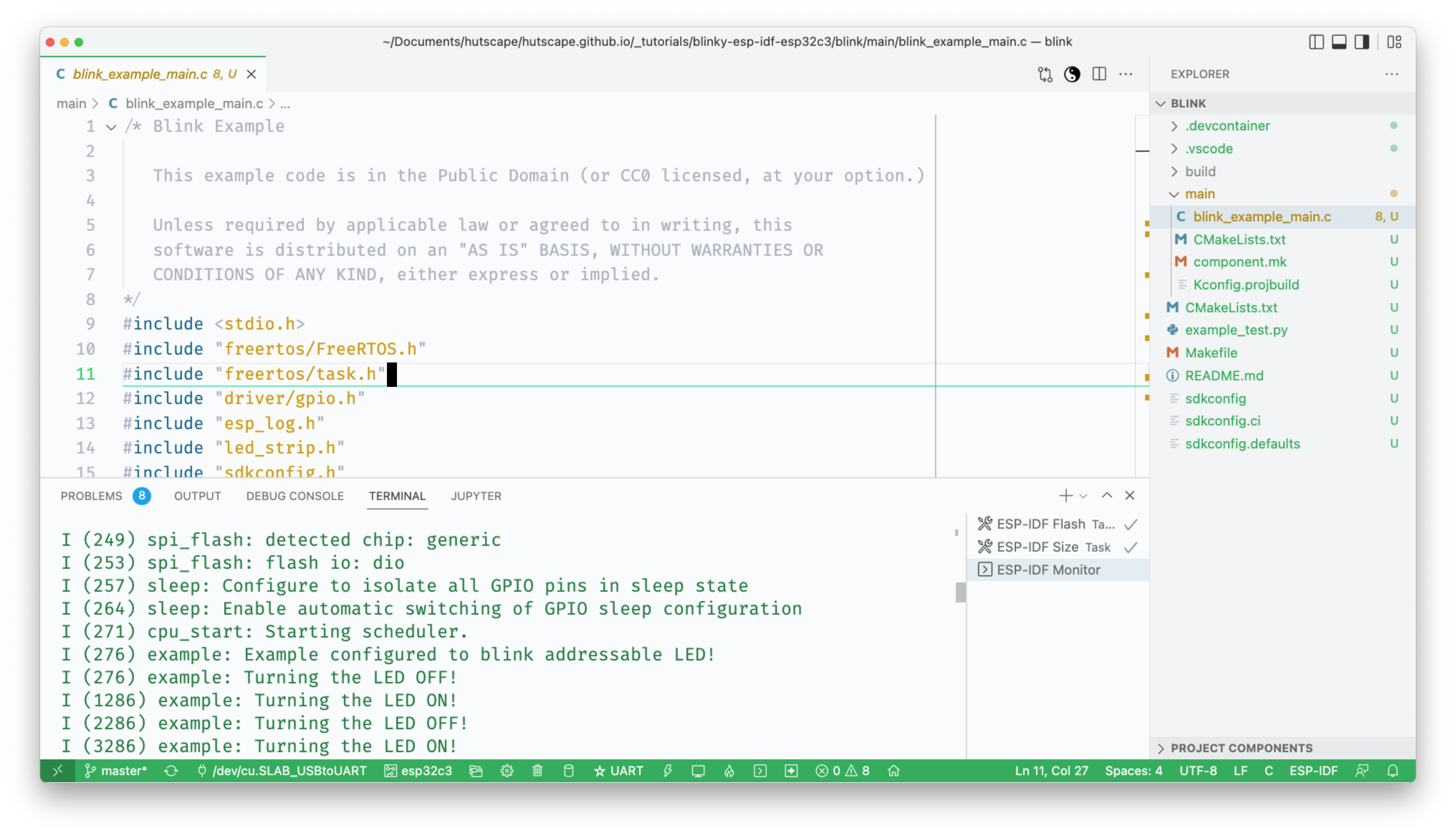
Serial console
Serial output from the firmware.
Dependancies
Buy the components
blink/main/blink_example_main.c
/* Blink Example

   This example code is in the Public Domain (or CC0 licensed, at your option.)

   Unless required by applicable law or agreed to in writing, this
   software is distributed on an "AS IS" BASIS, WITHOUT WARRANTIES OR
   CONDITIONS OF ANY KIND, either express or implied.
*/
#include <stdio.h>
#include "freertos/FreeRTOS.h"
#include "freertos/task.h"
#include "driver/gpio.h"
#include "esp_log.h"
#include "led_strip.h"
#include "sdkconfig.h"

static const char *TAG = "example";

/* Use project configuration menu (idf.py menuconfig) to choose the GPIO to blink,
   or you can edit the following line and set a number here.
*/
#define BLINK_GPIO CONFIG_BLINK_GPIO

static uint8_t s_led_state = 0;

#ifdef CONFIG_BLINK_LED_RMT
static led_strip_t *pStrip_a;

static void blink_led(void)
{
    /* If the addressable LED is enabled */
    if (s_led_state) {
        /* Set the LED pixel using RGB from 0 (0%) to 255 (100%) for each color */
        pStrip_a->set_pixel(pStrip_a, 0, 16, 16, 16);
        /* Refresh the strip to send data */
        pStrip_a->refresh(pStrip_a, 100);
    } else {
        /* Set all LED off to clear all pixels */
        pStrip_a->clear(pStrip_a, 50);
    }
}

static void configure_led(void)
{
    ESP_LOGI(TAG, "Example configured to blink addressable LED!");
    /* LED strip initialization with the GPIO and pixels number*/
    pStrip_a = led_strip_init(CONFIG_BLINK_LED_RMT_CHANNEL, BLINK_GPIO, 1);
    /* Set all LED off to clear all pixels */
    pStrip_a->clear(pStrip_a, 50);
}

#elif CONFIG_BLINK_LED_GPIO

static void blink_led(void)
{
    /* Set the GPIO level according to the state (LOW or HIGH)*/
    gpio_set_level(BLINK_GPIO, s_led_state);
}

static void configure_led(void)
{
    ESP_LOGI(TAG, "Example configured to blink GPIO LED!");
    gpio_reset_pin(BLINK_GPIO);
    /* Set the GPIO as a push/pull output */
    gpio_set_direction(BLINK_GPIO, GPIO_MODE_OUTPUT);
}

#endif

void app_main(void)
{

    /* Configure the peripheral according to the LED type */
    configure_led();

    while (1) {
        ESP_LOGI(TAG, "Turning the LED %s!", s_led_state == true ? "ON" : "OFF");
        blink_led();
        /* Toggle the LED state */
        s_led_state = !s_led_state;
        vTaskDelay(CONFIG_BLINK_PERIOD / portTICK_PERIOD_MS);
    }
}A photo of the actual setup.
Serial output from the firmware.
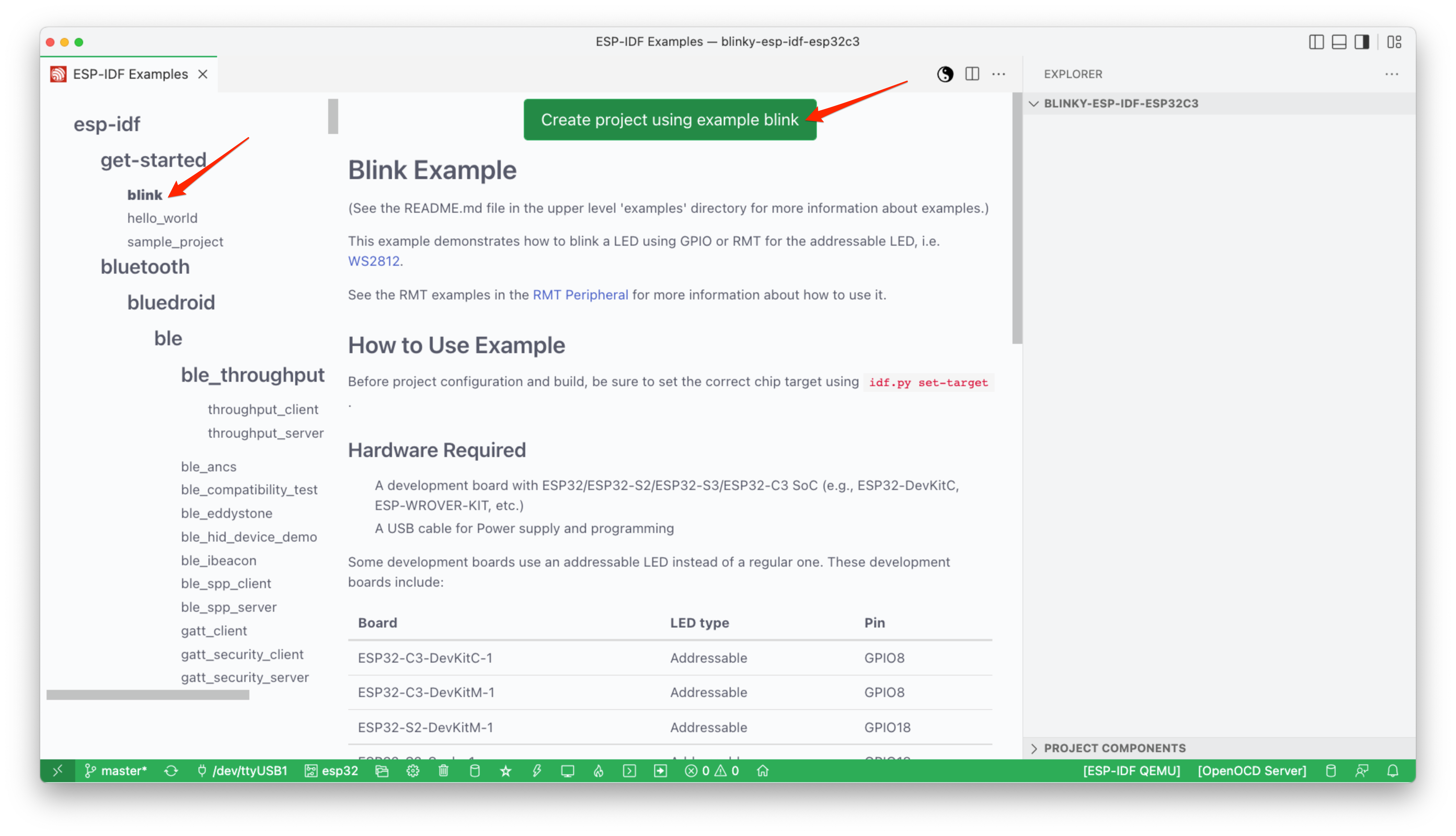
ESP-IDF: Show example projects

blink as the example project
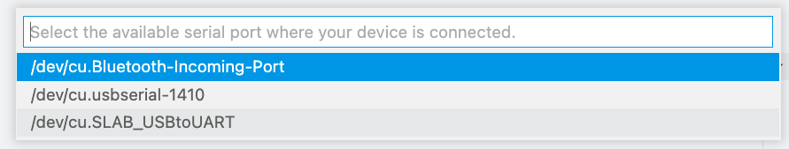
/dev/cu.SLAB_USBtoUART in the bottom green status bar icon 🔌
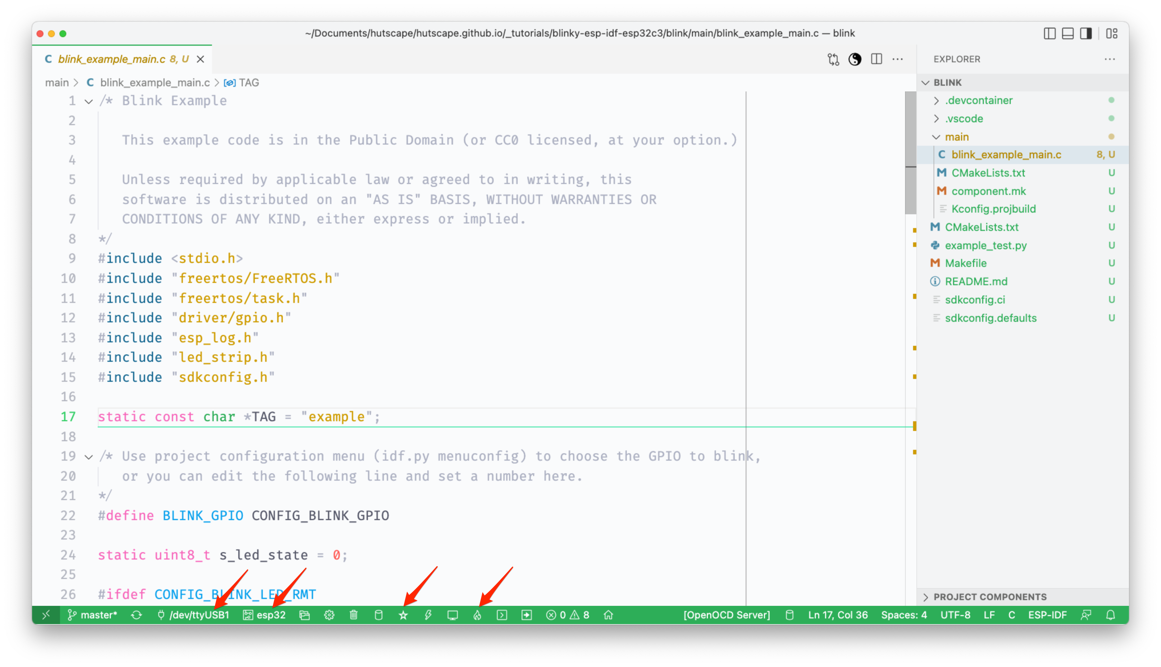
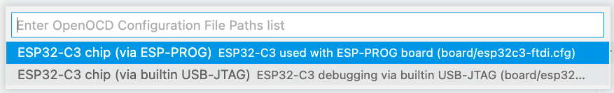
esp32c3

ESP32-C3 chip via builtin USB-JTAG)
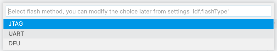
UART as the flash method in the bottom green status bar icon ⭐️